Fortunately, the manual of the Wavetek has some detail on the leveler correction PROM. Essentially, it is fed with 8 bits representing the frequency, 255 (0xff) for 7.0 GHz, 0 (0x00) for 12.4 GHz. For each of the 256 steps, it has a correction byte stored in a Texas Instruments TBP28L22N 256×8 PROM. This is programmed at the factory, to match each individual RF deck.
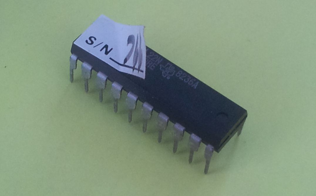
Getting this exact device and programming tools ready was out of question, some of these PROMS might still around, with datecodes of the 80s, but really not worth the effort and cost.
Step-by-step
Step (1) – A little test rig was set up, with the recently repaired HPAK 8904A as a DC source (can source -10 to +10 Volts, in very fine steps), and the DC voltage connected to the leveler correction control voltage line. The Wavetek is designed for servicability, and there is a nice jumper to disengage the actual level correction DAC, and the feed an external voltage instead. An EIP 545A was used as a frequency counter and power meter. Cable and EIP 545A power meter accuracy was tested with my best calibrated source at hand, and found to be within +-0.5 dB over the 7 to 12.4 GHz band.
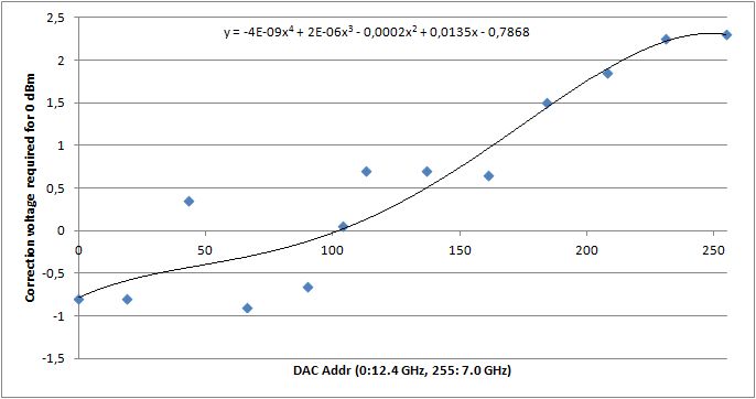
Step (2) – Data were collected by setting the Wavetek to various frequencies, mostly in 0.5 GHz steps, and the control voltage was adjusted for the power meter to read about 0 dBm. The data were then used to calculate the coefficients of a forth degree polynomial, and converted to the 256×8 bit format. The Wavetek uses a DAC0800LCN DAC, and the output voltage (after the on-board opamp, a LM307N) was found to be very close to 10.00 V with 0xff input, and nearly -10.00 V, for 0x00.
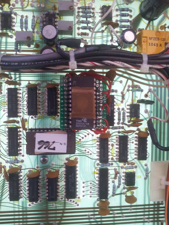
Step (3) – The tricky part. How to get a replacement for the 28L22 PROM? There are mainly two choices, one option would be to use a little microcontroller, that can easily function as a pseudo-memory, or use something more permanent, in this case, an EPROM. I had some 2532 around, therefore, not much effort. Only a small fraction of the 2532 will be used, 2 kbit of a total of 32 kbit. What a waste!
Unfortunately, the 2532 isn’t close in size to the 28L22, nor are the pins arranged in a similar fashion – but this can be solved with a little adapter board, and a few wires. Not the most beautiful solution, but who cares, it works!