
Others have explained at length the theorical background of magnetic leviation, and the associated regulator maths. I don’t want to get into this here – feel free to ask, I will explain it to you.
The goal: an apparatus that can hold a sphere of at least 1 kg mass (about 60 mm diameter, 2 1/2″) suspended from the pole of the magnet, in a distance of at last 25 mm/1″. It should be adjustable to hold also other parts, and not restricted to magnets (many of the available hobbyist leviation circuits can only hold magnets).
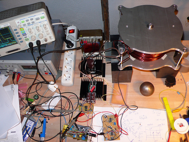
With the goal set, and after some calculations, related to electric magnet, heat dissipation, allowable maximum temperature for free air operation, time constants – the coil: about 10 kg of copper, of roughly 3 mm diameter wire. I selected a high-temperature type W210 isolated copper wire, this will withstand long term use even if the coil is operated permanently at full current. Don’t worry about the space the 10 kg will take, copper is very dense… Winding it can be a bit tough, as always, ask a friend for help, and best wind it with the help of a lathe (by manually turning it), or some other makeshift fixture. Winding it free-hand is not a good choice, because you won’t get a nice and tight coil.
For the circuits, these were build in modular style:
(1) The position detector – based on an infrared LED, and infrared photodiode, and fully independent of the lighting conditions. Is uses a modulated emitter, and a frequency-selective detector. It needs to have a reasonably fast response, and low noise/drift, otherwise, the regulation loop will be unstable – the sphere will start oscillating, and drop off.
(2) The position regulator – this is a classical PID regulator, build using a few TL074 opams. It compares the position setpoint and acutal position (from position detector, item 1), and determines the current needed to hold the sphere stable (current setpoint signal).
(3) The current regulator – this circuit converts the current setpoint signal into a drive current for the coil. To avoid undue powder dissipation in the regulator, this is achieved use a classic TL494 PWM regulation scheme. There is also a current limiting circuit, build-in, with a 0.050 Ohm 4-lead sense resistor in the coil current loop, and an AD620 instrumentation amplifier.
(4) Some auxilliary circuits – to switch off the magnets by disabling the current regulator, if there is no object attached. Otherwise, the magnet would run at full current, if the sphere drops off, and dissipate a low of heat for no good reason. Some power supply circuits – to provide 12 V power for the regulators, and unregulated 35 V to drive the magnet.