The Micro-Tel SG-811 and 1295 are great units, however, they lack PLL control. Even at their time, in the late 70s, early 80s, government labs required PLL control – and Micro-Tel offered PLL controlled frequency stabilizers for these units. Stabilizers that are now virtually impossible to source (if you have two spare Micro-Tel FS1000, please let me know!).
So I decided to build some very broadband PLL circuits that can handle 2 to 18 GHz, at reasonable frequency resolution. 10 kHz, or 100 kHz resolution seems to be perfectly adequate; mostly, the attenuator calibrator will be used in 2 GHz steps anyway.
Both units have two inputs:
(1) A frequency control input – a voltage controlled input, 0 to 10 V, that sets the frequency roughly, within the given band. Bands are: 2-4, 4-8, 8-12, 12-18 GHz. There is some thermal drift, but preliminary test shows that a 16 bit DAC would be most suitable for this kind of “coarse” frequency control.
(2) A phase lock input. This has a sensitivity of a few MHz per Volt. 0 to 10 V input, for the 1295 – and -3 to 3 V for the SG-811, as it turns out. Accordingly, with the coarse control set to the right value, the phase lock voltage should be somewhere around 3-7 Volts, for the 1295, and close to 0 V for the SG-811.
Now, the tricky part, how to get a phase comparator running, for the 2-18 GHz range? Traditionally, this requires a broadband harmonic generator, locking to a certain harmonic, and so on. All possible, has been done before, but a lot of work to get it working.
There comes the rescue, from Analog Devices: a truely remarkable little thing called ADF41020. It is a full 18 GHz PLL circuit, works with more or less any reference (10 MHz will be used here), and has pretty high input sensitivity, all that is needed are about -10 dBm to drive it over the full band.
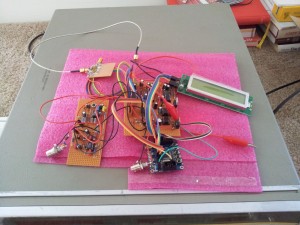
After some tricky soldering, in dead-bug style, and some auxilliary circuitry, with 16 bit DAC, reference voltage supply, very clean and stable supplies for the PLL, all the typical loop filters (0.5 KHz bandwidth) – and an ATMega32L – this is the current setup, for the 1295. Believe me, it is working just fine, and even has an auto-track feature, to keep the phase lock voltage mid-range – so it won’t un-lock with drift.
Upper left hand corner: ADF41020
Lower left hand corner: PLL loop filter
Center: Low noise voltage regulators, reference and DAC
Other parts: ATMega32L board (16 MHz, USB interface), LCD display (just for troubleshooting)

