
The position regulator takes the output from the position sensor, and converts it into a voltage drive signal. Nothing fance-it is just an opamp implementation of a PID regulator.
Brief description:
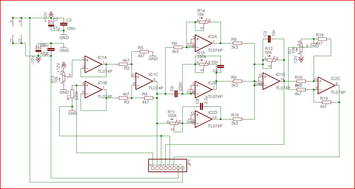
The position signal is connected to JP1-8, and converted to a 0-referenced voltage, relative to the desired position setpoint (R13, 10-turn pot), using IC1A, 1B and 1C.
JP7-1 provides this shifted signal for monitoring (position error signal). Opamps IC2A, 2B and 2D for the proportional, differential, and integral parts of the PID regulator. The P-component is made user-settable via R14 – a 10-turn pot. The other components only need some initial adjustment, depending on the coil you are using (C5 and C8 might also need adjustment; use high-quality capacitors, Mylar or similar). IC1D sums all the regulator components, and has R12, another 10-turn used-adjustable pot for total gain adjustment. Total gain is the most critical adjustment, if you change the type/weight of the suspended part.
IC2C adds a constant offset-just to prepare the signal (available at JP1-3) for the current regulator. JP1-5 has the intermediate current regulator setpoint, for monitoring purposes.