
The Micro-Tel 1295 has a GPIB (IEEE-488) interface, and in principle, can be fully controlled through this. In principle, but, not with ease; and, as it turns out, the build-in processor is running on 70s hardware, and doesn’t respond well to my National Instrument GPIB card. The only thing I need are the attenuation readings, in dB, same as shown on the front LED display.
Also, these GPIB cards are expensive, and I would rather like to control the whole attenuator calibration rig through one single USB port – also to be able to run in with various computers, not just with a dedicated machine.
In brief, after trying hard, I gave up – there need to be a more practical way to read the 1295 data.
First, how to get the data out, if not through the IEEE-488 interface? The case if fully closed, and drilling a hole, mounting a connector – NO. The modification should be reversible.
But there is a solution – the band selection connector, which is already used to remotely control the band switching, has a few spare pins!
This connector is a sight by itself:
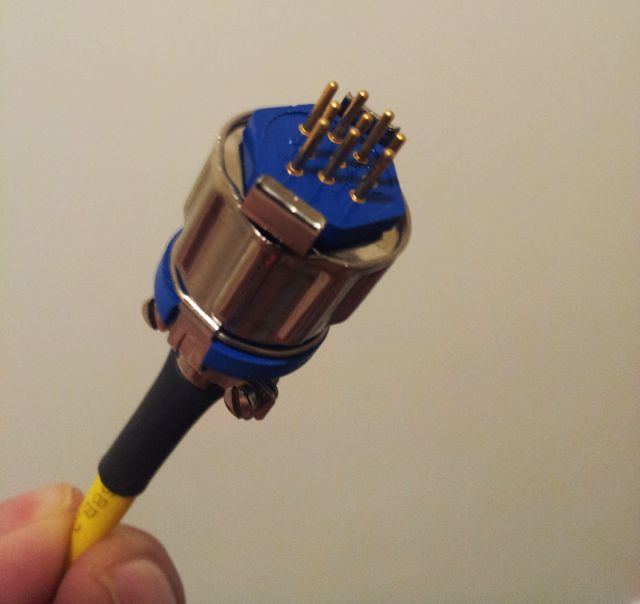
AMPHENOL/Wire-Pro “WPI” 9-pin “126 series” miniature hexagonal connector, 126-220; these connectors have been introduced in the 1940s, or latest, in the 50s. Still, available today… but the first piece of test equipment that I have ever seen that uses such kind of connectors. 500 Volts, 7.5 Amp – seems like a lot for such a small connector, at 14.99 USD each (plug only).
So, how to run the full display info over one or two wires? Update rate is 1 reading per second, or 1 reading every 4 seconds, not a lot of data – still it needs to be reliable, easy to use.
After some consideration, I decided to use a RS232 interface, with TTL level logic (rather than RS232 voltage levels-only using a short cable), and running it at 2400 bps, transmitting the data from the 1295 receiver to the main micro. This main controller, an ATmega32L can easily handle one more incoming signal, via its USART, and buffer any data coming from the 1295 before it is requested over the USB bus, by the PC software.
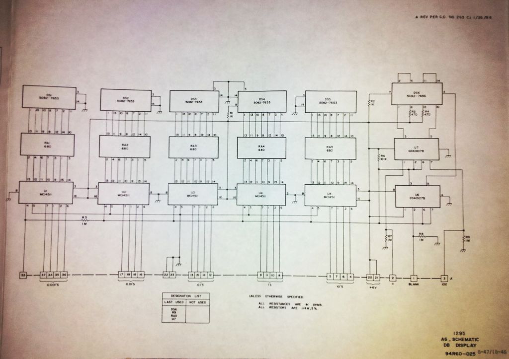
There are 5 full digits, plus a leading 1, a optional “+”, a leading-0 removing signal, and a blanking signal, which is set to low when the display is updating, or when the receiver is not giving a valid reading (over/underrange). Each digit needs 4 bits, binary coded decimal (BCD), so in total: 5×4+4=24 bits. Perfect match for the A, B, and C ports of a ATMega32L. This micro will monitor the blanking signal, and after sensing an updated display, read out the BCD information, convert it into a readable string, and send it out at the 2400 bps, via a single wire, no handshake, or anything. Will just keep on sending.
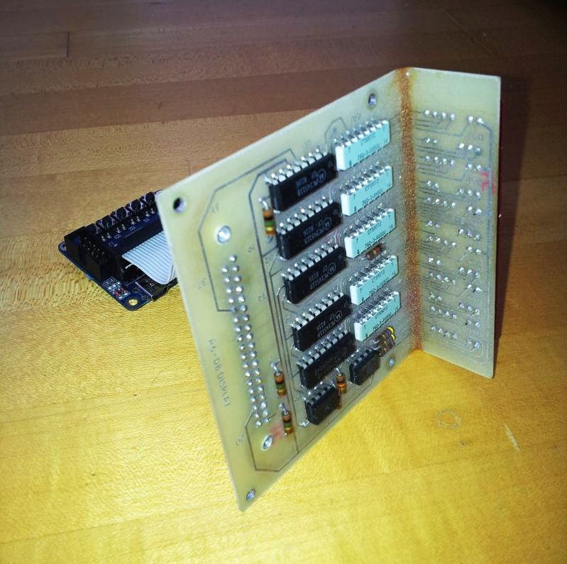
The easiest way to get the signal was determined to be directly at the display unit (A7) itself.
There is also some space to fit the micro board, a commercial (Chinese, called “JY-MCU”, Version 1.4) ATMega32L minium board, with USB connection. These are really great, running at 16 MHz, with some little LEDs (which are on port B – disabled for this application), and a bootloader. It just saves a lot of time, and these boards are really cheap, below $10.
A 34 pin ribbon cable, with double row connector, salvaged from an old PC – so the controller/parallel-to-serial converter can be removed from the 1295 if no longer needed, and even the cable de-soldered.
The modified assembly
MC14511 CMOS latches-BCD decoders-LED drivers – very common for 70s/early 80s vintage, and still working great!
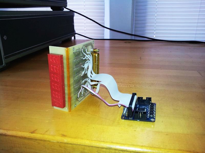
Data is being transmitted, no doubt:
Now it is just a matter of some lines of code, and soon, some real insertion loss tests can start! Stay tuned.