
With the basics done (power supply, potentiometer), a few hours were spent to get everything tuned up.
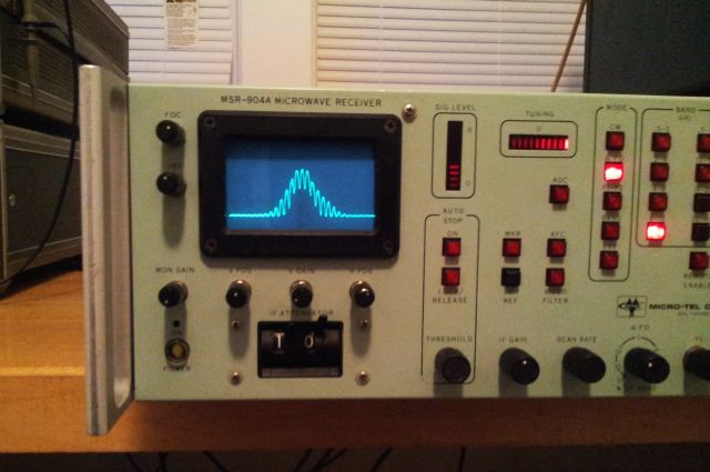
And, quite amazingly, it is receiving:
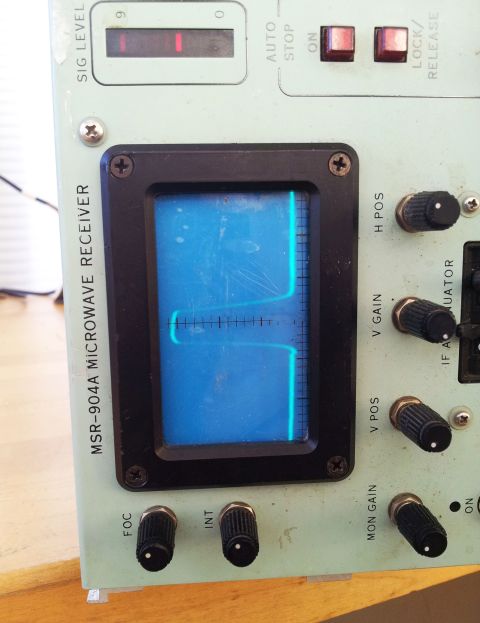
– notice the dirt, and the sticker residues. Also the crosshair (which is printed on a piece of plastic foil), will be replaced.
Finally, the exterior. The front panel, easy enough, all brushed and cleaned with diluted isopropyl alcohol.
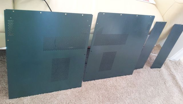
The top, bottom and side panels with the sticky green stuff – all the old junk (“paint”) has been removed, my soakin the panels in methylated sprits, sanding, solvent cleaning, sanding. Then, a layer of aluminum primer (self-etching automotive primer). Followed by a light sanding, and a layer of ‘Hunters Green” alkyd paint. After 10 hours of air drying, final curing at about 150-170 deg C, for a bit over an hour.
All in all, quite an effort. The result –
Missing items – one fastener like this – no idea where to find, seems like a part from the aerospace industry.
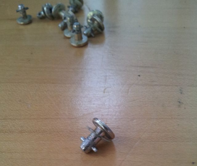
Should you have any of these around, even of somewhat different length, or if you know a source, please let me know!
Sweeping test around 8.1 GHz – with the refurbished panels installed.
Two more handles are still needed – either need to get spare handles from a parts units (which may be impossible to find), or ship the MSR-904A with 2 handles only, and provide the remaining two later, once I had a chance to fabricate them back home in Germany. At least, I have the exact dimensions measured, just a matter of some CNC milling.
-this is a test using a 8.1 GHz AM modulated signal, with about 1 kHz modulation frequency. Carefully checked the IF chain (different chains are used, depending on filter setting) – the MSR-904A uses 250 MHz, 160 MHz (by mixing the 250 MHz IF with 410 MHz, from a low noise LO), and 21.4 MHz (for the 100 kHz BW setting).
All seems to be functional.
With the receiver now basically functioning – some weekness of the AFC circuit alignment, and the frequency control was noticed. Therefore, some more effort was spent on the frequency control and AFC circuits, and the tuning indicator circuits. Really tough without any instructions or schematic.
There are some nice indicators on the front panel, LED bar graph displays – one for signal strength, and one for tuning.
These displays, now, in working condition and properly adjusted, are great fun to use. They are extremely responsive – nothing to compare with the time lag and sluggish nature of a modern SDR.
After several hours – here, receiving at 6.1 GHz, with 1 MHz bandwidth, and the AFC keeping the frequency, counteracting artificial drift:
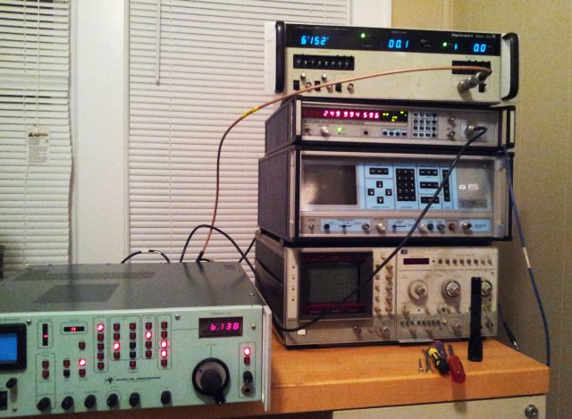
Monitoring of the AFC control is by looking at the IF frequency, 250 MHz (on the EIP 545A counter), derived from the (non-phaselocked) MSR-904A LO frequency, minus the RF input frequency (from the Gigatronics 605 Microwave Synthesizer; the EIP 545A is locked to the 10 MHz signal from the 605).
This setup allows me to check for any drift of the MSR-904A IF chain (and AFC, if activated), to 1 Hz resolution.
Had it running now for several hours, no issue, signal stays perfectly tuned.
The only remaining item, internally, is the alignment of the cross-band assembly – still lacking one CD4051 multiplexer circuit – which is on its way. A quick check with a CD4051 taken from another board showed that there is no defect, the board just needs some alignment of the band-to-band transition points. The crossband assembly allows a full 0.5-18 GHz sweep, with automatic band selection.