The 0 to 40 GHz SDR: Micro-Tel 1295+R820T USB RTL SDR

Having repaired two Micro-Tel 1295 microwave receivers recently, I noticed a IF (intermediate frequency) test port – this as a sample of the 30 MHz IF signal, from fundamental mixing of the input with the LO, for 0-18 GHz. Using 2nd and 3rd harmonics, and external mixers, the full range up to 40 GHz can be covered.

micro-tel 1295 if port

The 1295, despite its sensitivity, is actually not build for reception of real-world signal – it is an IF subsititution attentuation measurement receiver. However, this doesn’t mean it can’t be use to receive GHz signals… Recently I have been working on a 2-20 GHz digitally controlled preselector, and adding this to the 1295 will already help to get pretty much excellent selectivity.

0-40 GHz rtl-sdr using a Micro-Tel 1295

Now, a quick test: the IF test port, which is normally terminated in 50 Ohms, needs to be connected to the RTL USB SDR. To avoid overload of the RTL SDR by mirror signals, a little Micro-Circuit PBP-30+ filter was added, the silvery can, on the ESD foam, on top of the receiver.

pbp-30+ elliptical bandpass filter

This filter has a 6 MHz passband, 10 MHz 3 dB bandwidth – plenty for the USB SDR. Using a test signal at 11.02 GHz, with neither the receiver nor the source phase-locked, this is the result:

sdr at 11.02 GHz

Divisions are 100 kHz, so there is a bit of drift. But keep in mind: 0.1 MHz for 10000 MHz, that’s just about 10 ppm! – and a PLL will be added to the 1295 anyway.

After all, maybe a good idea to build a little 2-20 GHz downconverter, using a YIG pre-selector (currenty being developed anyway), a mixer and a LO (possibly using harmonic mixing). Stay tuned!

A quick look at the HP 5086-7259 YIG Oscillator: 2.0-4.5 GHz, 15-18 dBm

For a project involving an harmonic mixer, a strong and quiet – low phase noise – local oscillator is required. Looking around, I found a 5086-7259 in one of my boxes, a popular part, used in some high-quality HP test equipment.
Unfortunately, no data around, and this might also be the reason why these often go for about 50 USD on xbay.

hp 5086-7259 YIG oscillator

After some study of the circuit, here a rough schematic. It is essentially a set of Zener diodes and filter caps, plus some high-quality resistors.
The thing needs a +20 Volt, and -10 Volt supply. Not a problem – typically, this would be provided by dedicated low noise regulators, from the 24/28 V and -15 V rails common in test equipment.

hp 5086-7259 schematic (5061-5426 board)

Some measurement of the tuning current – it needs about 42 mA at 1.8 GHz (seems to work below the specified 2 GHz), and about 110 mA at 4.6 GHz – therefore, sensitivity as about 43 MHz per 1 mA.

Doing a quick calculation – setting the frequency to 1 MHz will required a DAC of about 12.5 bits resolution. Using a 16 bit DAC for the coarse tune current will be perfect, about 70 kHz per LSB; with phase lock on the FM coil.

The output power is quite substantial, about 15-18 dBm. Here, operated at the low end of the range, about 16 dBm:

5086-7259 output

Figuring out the details of the Avantek S082-0959 YIG filter

For a small job, I need to design a digitally-controlled YIG preselector (a high-performance bandpass filter), for the 12.4 to 18 GHz range. The application is related to a test rig, and only 4 units are needed – at low cost, and controllable by USB. The control will be easy enough, just a programmable current source and some parameters, but first, finding a suitable YIG is quite a challenge – either only single pieces are available surplus, or they are new, and prohibitively expensive.

Remembering some earlier work, I had a look at the S082-0959 – these were made by Avantek, and are available, scavenged from old spectrum analyzers, for about 200-300 USD each, and still have one spare around here. The S082-0959 is also known as YF85-0107, or HP 0960-0473 (pinout may vary).

To get started, first the basics need to be figured out. Tuning sensitivity, bandwidth roll-off (need at least 12 dB/octave; and >50 dB spurious).
The thing has two pairs of connections: heater (2 wires) and coil (2 wires, this sets the magentic field – the tuning, via current – not voltage – control).

Looking at some spectrum analyzer schematics – the heater needs about 28 V. And, in fact, it works well and heats up quickly, drawing about 80 mA at 28 V, less with strong coil current applied (more during heating-up).

YIG filter Avantek S082-0959

The test setup – two power supplies, a counter EIP 545A, a microwave source EIP 928, and a microwave receiver Micro-Tel 1295. Signal level was 0 dBm.
The coil supply has a 4.7 Ohm current sense resistor, I’m measuring the voltage drop to calculate the current.

For 10 GHz, the tuning current was found to be about 132 mA, about 75.8 MHz/mA sensitivity.

Measurement result of insertion loss vs. frequency –
s082-0959 yig insertion loss vs frequency at 132 mA
– note that the passband is not well captured, but 3 dB bandwidth has been measured, by manual tuning, about 25-30 MHz. Recordering accurate values is a bit troublesome, would need to phase-lock the microwave source and receiver.
There is a spurious signal, about 350 MHz above the center frequency. This I will need to investigagte further. Note that the measuement points are not arbitrarily selected, but the YIG was actually tuned for the minimum loss, and the maximum response of the spurious.

Calculating the roll-off (25 MHz assumed 3 dB bandwidth):
s082-0959 yig roll-off at 10 ghz

As you can see, when doubling the bandwidth (e.g., from 2x to 4x – don’t look to close to the center frequency), the signal is about 20 dB down. That’s close to 18 dB per octave.
Without going into theory, which can be found elsewhere, a one-stage YIG filter will give (ideally) about 6 dB per octave. So the S082-0595 is most likely a 3 stage (3 sphere) filter. Well, limited accuaracy – the YIG will be fully characterized, once things are more advanced.

Micro-Tel 1295 Precision Attenuation Measurement Receiver: cleaned, painted (!), fixed, modified, and fully adjusted/calibrated

The 1295 receiver – before working on the internals, the external parts – the panels – needed a makeover.

(1) Sticky paint removed from side panels, top and bottom panels, using methylated sprits. Imaging scraping off dark green chewing gum, several square feet covered with it. Hope the company that sold this paint is now out of business, that’s what they deserve.

(2) Some more cleaning and sanding, with 400 grit paper.

(3) Primed with self-etching automotive primer. For coating aluminum metal, always use a suitable primer – don’t trust any suggestions on paint cans that it will work without a primer. It won’t.
After some drying, a quick sanding. Not aiming for perfection.

(4) Top coat with a modified alkyd resin. “Hunters green” appears close to the original color shade.

(5) After several hours air-drying, burn-in at about 165 °C, for 60 minutes. This improved adhesion, at least based on my past experience, and no need to wait for days before the instrument can be re-assembled.

(6) Clean the newly painted surfaces with isopropylic alcohol, this gives an even shine, and to confirm that the new paint is fully resistant vs such solvents.

(7) Re-assemble all the small hardware and screws, feets, etc, of the panels!

The other items:

(1) Added filter caps to the YIG driver, when under remote control (more or less a bug in the Micro-Tel circuit).

(2) Added a parallel ot serial converter to the display – the readout values are now transmitted via 2400 baud, via the external control connector. See post in the attenuation measurement section. The circuit involves an ATmega32L which monitors the display for an update, and with every update occurring, it reads out the value, and does the transmission – no handshake.

(3) All frequency related and AFC adjustments, YIG driver adjustments etc. have been performed. Calibration of attenuation levels checked – seems OK – precise calibration, I can only do back in Germany. But seems to be in-spec, and will compare more throughly vs the “master” 1295 – the first unit.

(4) The light of the mains switch, using a T1-1/4 28 V 0.04 V incandescent bulb, with broken filament – replaced by a LED, with an added 1 k resistor in the supply line.

(5) Fitted a spare 2″ display bezel, with red filter – the original one was missing.

That’s the gem, receiving at about 16.260 GHz.

1295 cleaned and painted

HPAK 1345A Digital Display: a great worry, and a shorted tantalum cap

The 1345A is almost a one-of-a-kind, not easily replaced by something else – it is a display unit designed by HP during the early 80s, and used in quite a few instruments that are still of value today. These instruments include various analyzers, e.g., 3577 series network analyzers, 356x series signal analyzers, 4145 semiconductor analyzer, and so on.

it takes in some 16 bit digital data, and converts it into strokes, which are then displayed on an electrostatic (!) CRT.
1345 block diagram

This repair, I almost wanted to refuse it, because with a description of “dark display”, typically, the CRT is at fault, and there is not much to be done about it – I have a few spare parts here, for the 1345A, but no CRT. My greatest worry, having to deal with things beyond repair.

Well, after some debate, the thing arrived and it has been gathering dust here. Now, I openend it up. Big surprise. The 15 V rail fuse of the 1345A was blown. Took a while to track down which of the various boards was causing the issue. Turns out, the A1 is shorting the rail.
Nothing suspicious was found, so I just left it powered with a current-limited supply, to feel where the power is going. A bit of smell. A 2.2 µF tantalum cap!!

For many other devices, failed caps are a common observation. Not so much for HP equipment, even after 30 years. Quick look at the parts list:
a1 parts list

The part specified is a Vishay/Sprague 150D series tantalum cap:
vishay 150d tantalum cap

As shown on the datasheet, these are very reliable, the best around. However – these are not the caps found in the 1345A. Maybe, at some point, HP switched to some cheaper tantalums (the 150Ds are about 2 USD each!).

With no axial caps around, all the tantalums were checked, and 1 found defective, 1 suspicious. These were replaced by electrolytic capacitors – good enough.
1345a a1 stroke gen xyz board replaced caps 2
Red frames: replaced caps, yellow frames: original tantalums, still working.

After putting back a good number of screws, a quick test, and, success!

1345a working display

Needless to say, following the old rule of first checking the power supply rails, and looking for defective caps, is still helpful, although it doesn’t usually help a lot (like in this case) when it comes to test equipment.

EIP 545A Microwave Counter: power meter upgrade

This time, not really a repair, but an upgrade.

Every lab or repair shop dealing with really high frequency circuits needs one: a microwave counter. The EIP 54x series has certainly been (and still is) one of the workhorses of the industry. EIP is now Phase Matrix, still selling counters. But I guess, not an easy tasks – there are quite a few of the EIP counters around, and they do have some little issues with tantalum capacitors, etc, but all in all, the EIP counters are really marvelous instruments, rock solid.

The 545A:
eip 545a counter

In my own shop, there are two 545A counters (18 GHz, N connector), and also a 548A, which is similar, but covers up to 26.5 GHz (3.5 mm connector). The 548A can go to frequencies as high as 110 GHz, with some external mixers. While these have provided good service over the years, they are all lacking ‘option 2’, the build-in power meter. At microwave frequencies, having a combined power meter and counter has a considerable advantage – no need for changing cables, no need for splitters or couplers – just the push of a button. And not always do you want to connect a circuit under test to a valuable 18 GHz+ spectrum analyzer or measurement receiver…

Fortunately, there are clever people around, at the Green Bay Professional Packet Radio club (“GBPPR”), which kindly provide the ROM images and some circuit modification info on the web – to convert a regular 545A, to an option 2 545A!

Well, first we need to collect some parts, a low capacity Schottky diode (HP 5082-2835, 1 pF max.; original EIP circuit uses a different kind, but really any low capacity Schottky will work), a DM8136N (a comparator/address decoder), a 74LS244 buffer, and an AD7524JN (8 bit DAC) – plus, a 10k resistor. Except for the DM8136N, nothing uncommon at all.

The only tricky part, at least here – the 2532 EPROMs. These aren’t accepted by any of the programmers around, and they need a high programming voltage. So first, put together a little programmer that attaches to an ATmega32L, and with the data transfered by USB.

2516 eprom programmer
It’s really crude – I don’t anticipate a lot more 2532 EPROMs that need programming, except for the EIP….
I had some 2532A around which are working perfectly fine, just lower programming voltage. The 2532A/2532 – they can be handled by some 2732 programmers, for reading the contents, with a little socket adapter (2532 and 2732 have different pinouts!) – but strangle, the same programmer doesn’t work for writing to the these old beasts.

The second type, they are 2516 EPROMs, no problem with a 2716 programmer.

After fiddling around with the EPROMs, the little programmer, the adapter sockets – a few hours later – that’s now the set of parts:
eip option 2 upgrade parts

These are the boards, A105 and A107, with the parts installed – red rectangles: additional parts; yellow: removed parts (resistors R39 and R40).
eip 545 board modifications

I would suggest to put all parts in sockets, like EIP did. Then you can change your counter back, to non-option 2, should you ever want to.

After a bit of soldering – that what we have – a working option 2 EIP 545A.
eip 545a option 2 power meter working
The power meter can be switched off – if you need the extra digits. Typically, I don’t.

All that is left are the original EIP EPROMs, programmed in San Jose, California. Collectables.

eip original eproms

Any questions, please let me know!

Micro-Tel 1295 Precision Attenuation Measurement Receiver: 2nd unit!!

Recently, I haven’t been acquiring a lot of test equpiment, for my own workshop aka museum, because space here in the US is limited, and carrying all these things over to Germany again in 1 or 2 years will be a hazzle. But this time, I could not resist – a Micro-Tel 1295 receiver, for less than 1 ct. per USD 1980s list price! The parts alone, a 2.33 GHz low noise LO, 2-8 GHz Avantek YIG, 8-18 GHz Avantek YIG, a 2-18 GHz broadband coupler, various microwave mixers and attenuators, all of the best mil-spec quality, well worth it.
Also, it will be a great addition to the precision attenuation test set-up: a dedicated receiver each, for the through and reflected power! And, we can safe one coaxial relais (to switch either through power, or reflected power, to a single receiver), and everything will be faster, by almost a factor of 2. The only downside – another PLL will be required, but well, this is just a matter of a rainy weekend.

It arrived well packaged, no damage, except a missing frequency display bezel (which was easy to source, exact fit), but one thing I did not expect: the paintwork on the upper and lower cover, and side panels, has converted into a mixture of honey and chewing gum, a sticky mess, and dark green! So, first task was to strip off this “paint”, which was pretty easy using some methylated spirits, and engage a bit in spray painting. Hunter’s Green.
micro-tel 1295 sticky paint
See the dark green side panel – covered with sticky paint! Now, it is finally clear to me, why the 1st unit, the 1295 acquired earlier, had been re-painted by his former owner….

Note that the lid and side panels have numerous screws and nuts (more than 100 single pieces!) – quite impressive, how little Micro-Tel had to consider manufacturing cost!

One issue found so far: the IF distribution relais had some intermittent noise – most likely a bad contact somewhere. So took out all the board, cleaned up the edge connectors (all gold plated), and moved the connectors around a few times – and, the issue is gone.

A note on edge connector cleaning: this is best done, from my experience, we some special type of eraser. Don’t use anything harsh, abrasive, or natural rubber. It will either scratch it gold coating, or leave traces of residue behind that isn’t going to improve contact resistance and reliability.
Best suited at vinyl erasers made especially for PET film or tracing paper. Prismacolor Magic Rub.
prismacolor magic rub box

These crumble a bit, but the vinyl materials absorbs all the dirt, and can be brushed of easily, with an ESD brush.

The unit is overall very clean, just the frequency calibration/display seems to be quite a bit off. This will be the next step, after a thorough warm up.

And, as for the first unit, I will add a parallel to serial converter for the display, same as for my main Micro-Tel 1295, because I don’t want to use the IEEE-488 bus for this device. It will have the same 2400 baud (TTL-level) serial output. Also, a little capacitor will be added, to limit the bandwidth of the Freq Control/YIG driver amp when in external mode – this seems kind of a bug of this device, because the larger bandwidth only increases noise, and the receiver is not build for fast sweeping anyway.

HP Agilent Keysight: missing instrument feed mystery

There is one thing that has always been inriguing me: why are most of the HP Agilent intruments that I am getting my hands on missing feet?

missing instrument foot

This is a picture from the recenty fixed HP 8782B. It has 3 feet installed, 1 missing –
HP Part No 5040-7201, 5041-8801, about USD 14 (each!) at Keysight.

Maybe, some sellers take them off, and sell them separately at xbay – same what is happening to the manuals. And in fact, some offers are posted, but by no means enough to explain all the missing feet everywhere.

Also, if equipment is rack mounted, sure, the feet are taken off and stored somewhere in a drawer at one of the big test labs army bases or corporations, but many of the intruments have never been rack-mounted…

Maybe some of the test engineers just can’t let go and hold back at least one of the feet! Well, I’m glad they don’t take out one of the transistors…

hp instrument feet

So in the end, if you happen to find a bag of these somewhere, please forward them to me…. to put them back where they belong.

HPAK (HP Agilent now Keysight) 8782B Vector Signal Generator: an easy fix

The 8782B is a quite powerful generator to simulate digital signals, not considering the power in dBm, but the support of all the common digital modulation schemes, BPSK, QPSK, 8PSK, 16/64/256 QAM, at exeptional signal integrity.
Frequency range is 0 to 250 MHz, actually, it works to 370 MHz – but this instrument is mainly intended to generate complex IF signals, which can then be used to test the IF chain of a receiver, or, you just add a mixer, another generator for the LO, and a filter, if needed, to get the signal up into the GHz region.

This unit arrived in a HUGE box, it just fits the car!

All frequencies are derived from a HP 10811E ovenized oscillator, which is held by a shock-absorbing mount, and is extremely stable (better than 0.5 ppb per day!), and low phase noise, resulting in below -125 dBc at 1 kHz from the carrier, and below -130 dBc further out.

The symptoms:

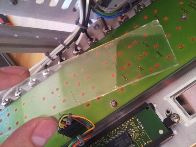
(1) The right LCD display is missing partial digits. Seems to be related to the mounting/contact of the LCD with the board.
8782b display defect

(2) Output is 30 dB down, but otherwise working just fine.
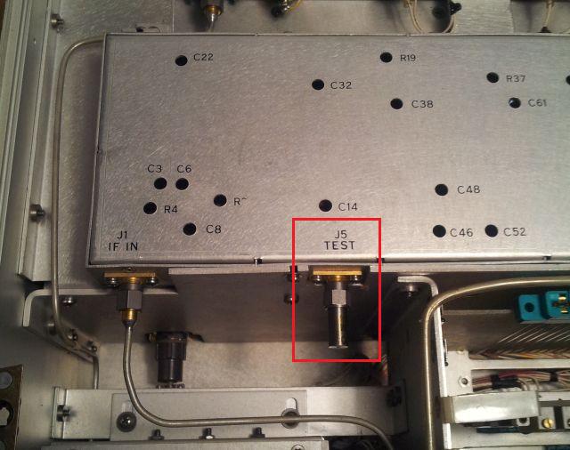
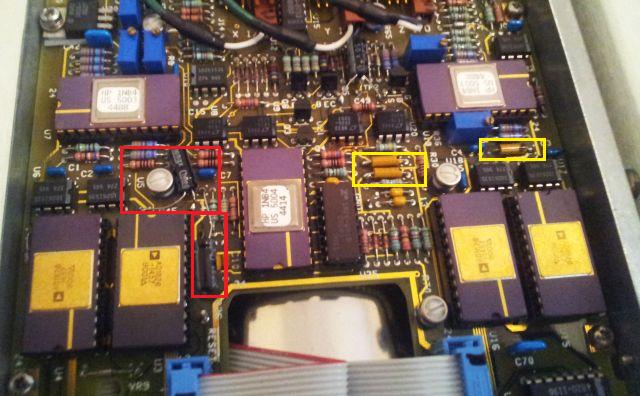
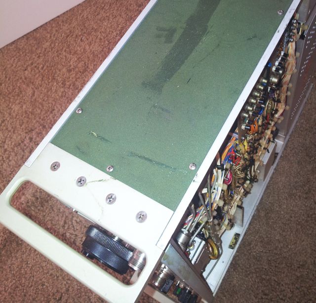
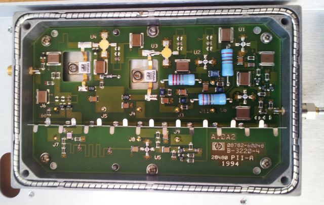
Quick look at the output amplifier – a real marvel of RF engineering.
8782b a10a2 output amp assy

(3) It’s in good condition, but will benefit from a bit of de-dusting and cleaning.

The repair:

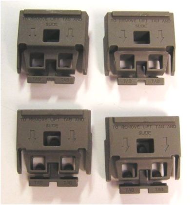
(1) After taking off the front panel, the LCD is a separate assembly, seems to be made by HP (which test equipment company would nowadays still make their own LCD displays?), and easy to remove. And, the defect, readily found. One of the side bars holding the assembly together and pressing the glass display to the control board, to make contact via an elastic strip, it had slipped off. The root cause – somebody must have used nail clippers to fabricate a piece of acrylic that is used to protect the LCD surface – maybe it was broken or scratched. And with the uneven edges, it caused tension on the display unit, pushing off the side bar.
8782b display protector
Well, Let’s just straighten out things and put it back together. No surprise, the LCD is working again just great.

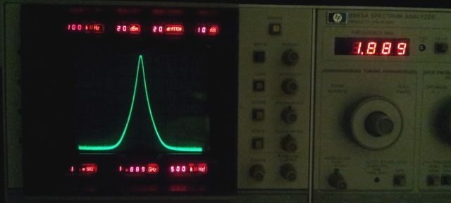
(2) The level control. According to the description of the sender, the output is about 30 dB down. Most likely, something with the attenuator, 08780-60093 = 33322GC, 110 dB, 10 dB step. So, the attenuator, easily removed, and the non-attenuated signal directly fed to the dated but very trustworthy HPAK 8565A spectrum analyzer available here at the bench. Now there is plenty of signal, but it isn’t accuarate at all, even relative steps, like 1 dB steps, give variable response, anything from 0.5 to 2 dB steps… The level spec of the 8782B isn’t all that great, but I know from earlier work with such units, the performance is much better than spec, and 1 dB step, should be 1 dB. Turns out, just a little pitfall, the 8782B has a calibration routine, also for the level, and somehow, this unit seems not to have been calibrated for a while. Well, easy enough, just pushed the “CAL” button, and after a few minutes, you bet, the levels are spot-on, and, within 0.1 dB or so.
Just a quick fix on the attenuator control circuit, and, the level is back.

(3) For cleaning, don’t use anything too harsh on these instruments, they use different plastics and pains compared to earlier HP models. I get good results with about 20-25% isopropylic alcohol (1 part of the alcohol, 3 parts of distilled water).

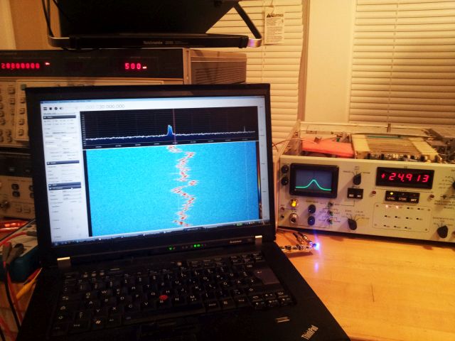
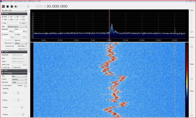
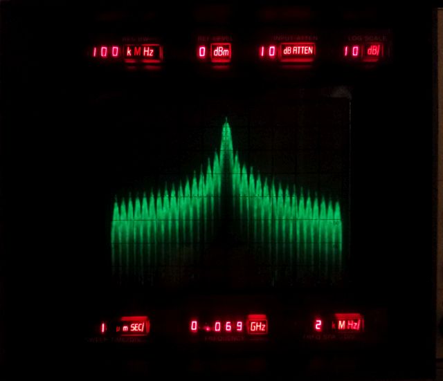
Some quick tests – all self tests passed OK – and here, a BPSK signal:

8782b bpsk test

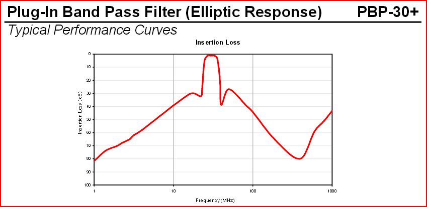
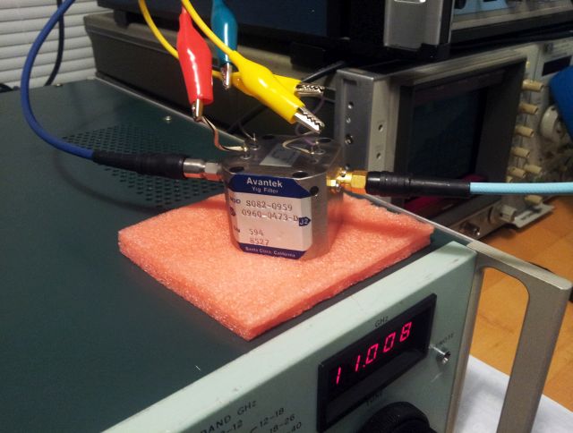
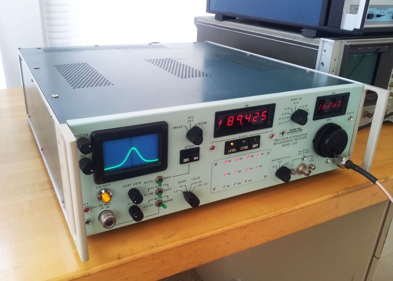
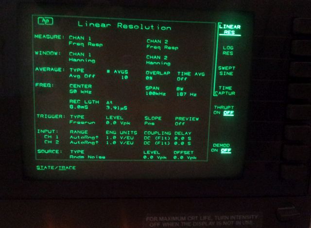
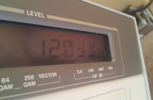
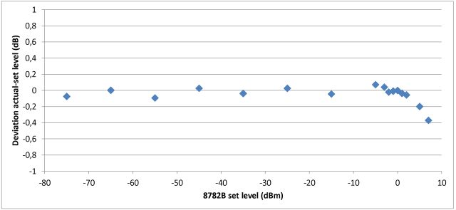
Level accuracy, all well within spec (measured with a Micro-Tel 1295):
8782b level accuracy test

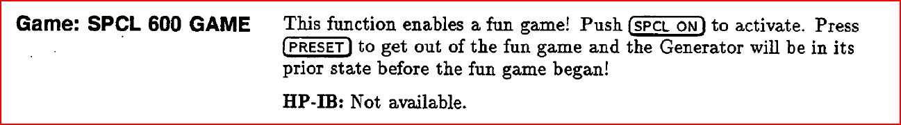
And, with the 8782B the boring times in the lab are over, Thank’s to the build-in game – everyone will be looking at you, working hard, pushing the buttons!
8782b special function 600 game

The best solution, most likely: let the nonlinearities (INL) cancel out

After putting a bit more thought into this, let’s have a look again at the kind of nonlinearity observed for the ADS1211. We only know three points where there will be no error due to non-linearity: the zero point (because that will be covered by the zero point calibration), and the plus (and minus) voltage, at which the gain calibration is carrier out. The gain will be calibrated both for the positive and negative direction, simply by reversing the same calibration voltage, most likely, about 7.x volts, supplied by a LTZ1000.

Again, from the datasheet:
nonlinearity ADS1211

Now, what if we measure not just with one ADC, but with two, of the same kind, and hopefully, with the same non-linearity, but, with the polarity reversed. I.e., because of the fully differential nature, we can measure, simultaneously, the same voltage, both in the positive and negative direction. Doing this adequately should cancel out most of the (integral) nonlinearity. Furthermore, if use two independent references, for the two ADC we will also gain noise margin – because some of the noise in non-correlated and will cancel out – also, we will acquire the same signal independently, and do the averaging digitally! For non-correlated noise, this means about 3 dB gain, about half a bit!

inversion averaging ADC scheme

It only means that finally, we will need to put in 8 ADCs to measure two voltages, but, well, who cares – the given application can handle this, specialized equipment, and no relation to the total cost. And, with some luck, it will result in linearity errors of better than 1 ppm, and 7 digits resolution, with pretty fast data rates.

inversion averaging ADC nonlinearity cancellation
The solid line: non-linearity of ADC1, the dashed line – non-linearity of ADC2, both ADC are running fully synchronized, same control codes to both ADCs. Two digital outputs – and, one output will be fully inversed, directly in the ADC controller (an ATmega32L), to yield the average of the ADC1 reading, and the complementary of ADC2. Sure the difference to 0 V can also be analyzed, to check how far off the individual values are.
The ATmega32L will also do some decimation, from 60 Hz, to maybe 5 Hz or 1 Hz (independent of the mains frequency), and sent the data to the main controlled, via an optoelectronic isolator (the full ADC section design with fully floating digital and analog grounds). 1200 or 2400 baud will be plenty to get the data out. 60 Hz 6 bytes would be 360 bytes per second, about 3600 baud (need to count start and stop bit), but with decimation, we don’t need any fast couplers, etc.

Sure, this is currently an idea, and will need a closer look, but I assume, it will do the trick, at reasonable cost.
If it works out, maybe we go one step back in the final implementation – the ADS1211 has a 4 to 1 MUX, and rather than sampling simultaneously – we might just give up the noise advantage, and sample consecutively, once with positive polarity, and then, via another channel, in inverse polarity. But hey, Texas Instruments will be happy to sell a few more ADCs.

Finally, not sure if it is better to run both ADC from the same 10 MHz clock, or from separate clocks – some of the jitter induced noise might average out only, if the jitter sources are independent. So many, option, but quite easy to find out!