After some experimentation, measurements, etc. – as described before, time to wrap it up.
The PLL loop filter output is now connected to the phase lock input (the additional 1 k/100 n low pass in the earlier schematic has been omitted), with a 330 Ohm resistor in series. This will remain in the circuit, because it’s handy to characterize the loop, and to provide a bit of protection for the opamp output, in case something goes wrong, to give it a chance to survive.
With the charge pump current adjustments now implemented in the software, that’s the result, all pretty stable and constant over the full range.
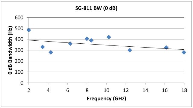
The SG-811 signal source
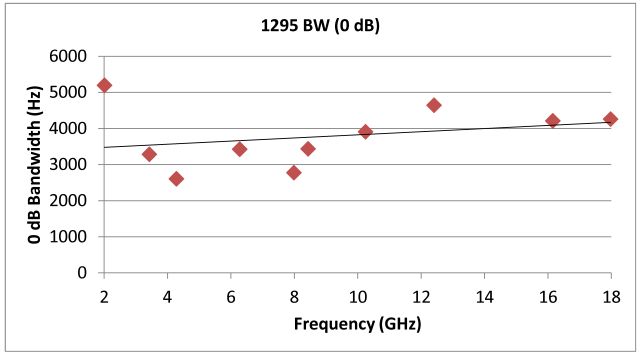
The 1295 receiver
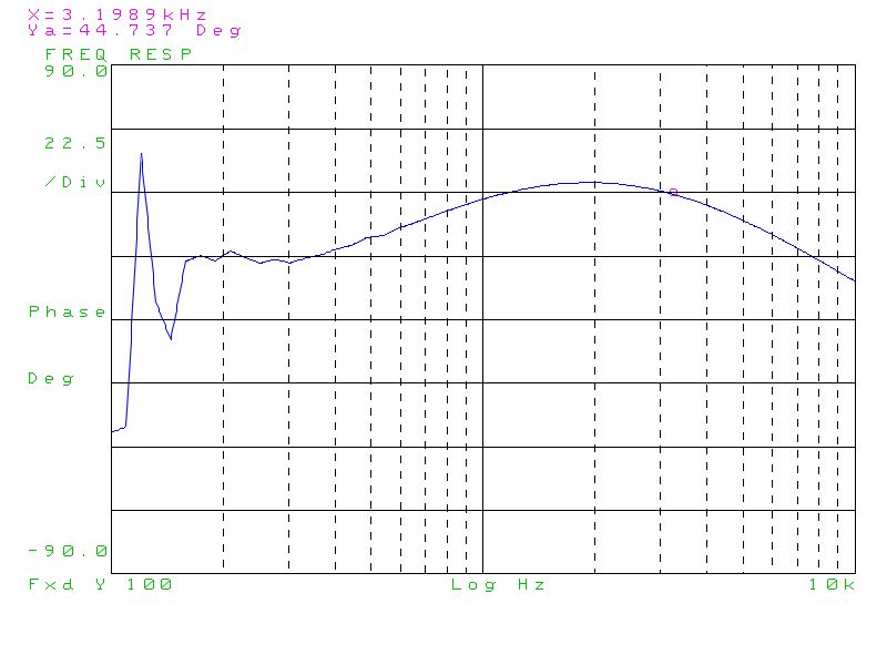
Micro-Tel SG-811 PLL: frequency response
Gain

Phase

Micro-Tel 1295: frequency response
Gain

Phase