
There are some good reasons to always carry one of the SDR USB sticks around – it’s a great little spectrum analyzer. But hold, what does it have in common with the purpose build-professional analyzers selling for USD 1k or more? It certainly has one particular advantage, the SDR USB stick is very small, a mere 10 gramms, and only needs about 1 Watt of power. And it covers the full span of frequencies of general interest (at least is you add an upconverter, for low frequency and HF stuff below 24 MHz).
Well, what are some key requirements of a good spectrum analyzer?
(1) No spurs, at least no unpredictable ones. Well, there are spurs, but mainly multiples of 28.8 MHz (reference), and some spures related to the sampling frequencies (always check if the spur changes, by checking out several sample rates that are not multiples of each other)
(2) Intermodulation distortion. More complicated, will be analyzed later.
(3) Low input return loss (otherwise, amplitudes will be inaccurate). Will be measured later, the VNA rests back home in Germany. But this limitation can be easily overcome by putting a 6 dB attenuator in front of the SDR USB.
(4) Frequency accuracy – this is not great, but stable within a few ppm. If you want to add a precision reference, see earlier post.
(5) Amplitude accuracy – it needs to be very linear (i.e., a 1 dB step in signal strength must convert to a 1 dB step on the readout, same for 10 dB steps, etc.), and this should not very too much with frequency. Absolute amplitude accuracy (i.e., if 1 dBm is fed into the RF input, it needs to read 1 dBm power) – not applicable to the SDR USB stick, it only shows power in nominal, un-calibrated dB.
Well, let’s tackle item 5, and work out some absolute calibration.
The R820T tuner of the SDR USB stick under consideration here has a build-in preamp. This has nominal gains from 0 dB, to 49.6 dB. Some gain curves have been reported for other SDR USB sticks elsewhere, let’s do some in-depth analysis.
How to get this measured properly? The setup and method:
With 1.024 MSPS, 65536 FFT bins, RF frequency of 1000 MHz (HPAK 8642B), reference at 28.80 MHz – 500 mV (provided by an HPAK 8662A) and gains set to values of 0 dB, 20.7 dB (about mid-range), and 49.6 dB (max gain), the input RF power (which is calibrated in absolute dBm, and fed to the SDR USB stick by a low-loss cable) is varied in 10 dB steps, and the dB reading taken from the SDRSharp FFT spectrum display. Note that fully accurate reading of the dBs is only possible if the frequencies (reference and signal) are dead-stable, otherwise everything will be drifting up and down, and the FFT bins won’t be in the same place all the time.
Here are the results:
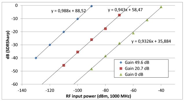
Everthing is quite linear (a good fit with just a line), but you notice, the slope of the lines change a bit, depending on the gain setting. In other words, a 1 dBm chain will not always result in an exactly 1 dB change on the SDSSharp display, at high gain setting, it will almost fit, at 0 dB, there is only about 0.93 dB change (readout) for every 1 dBm power change at the input. Well, over 40 dB, that’s an error of about 3 dB, not much, but more than desirable.
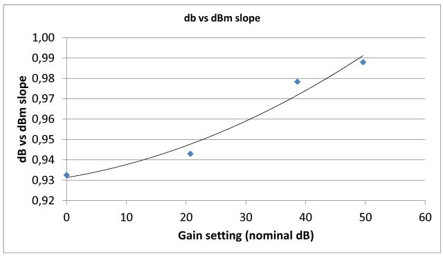
r820t level accuracy
After some more measurements, at 38.6 dB nominal gain, it relationship of level slope vs. gain seems pretty clear, at least at 1000 MHz.
After applying the slope correction (comparing a linear fit, with the acutal measured data), these are the residuals:
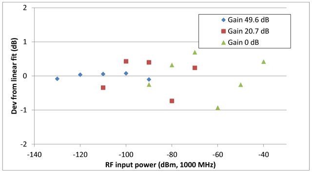
Less than 1 dB – that’s within the measurement error of the calibration apparatus!
Next interesting item for practical use, the RF input power needed to get a 0 dB reading – the absolute power calibration for this SDR USB stick. This seems to vary from stick to stick only by 2-3 dB, but I don’t have a big set of sticks, multiple lots etc. – so this might be shifted depending on the exact device you are using, but trends should be the same, for all R820T sticks.
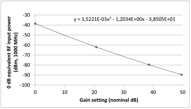
According to this diagram, for any measurements above -40 dBm, you need a good set of attenuators, to bring the signal level down. In fact, the SDR USB might actually make a very decent subtitution type attenuation test receiver, if you put it in line with a precision attenuator, and only use a few dBs of span of the SDR USB (well-calibrated) to determine the signal levels. I checked quickly for drift of the level calibation vs. R820T temperature – there doesn’t seem to be any strong effect, which is a good sign that there is no need to re-calibrate the levels all the time.
One thought on “R820T, RTL2832U SDR USB stick: using it as a “poor man’s” spectrum analyzer – level linearity, level accuracy”