The manual for the 8569A describes a series of performance tests – not all of them were completed, but most. Fortunately, the IF chain doesn’t need adjustment. Still, it took nearly three hours to get the YTF tracking, the A/D converter/digital display section and other display related circuits adjusted. The log amplifier was carefully tested as well, all perfectly in tune.
The most amazing find – the internal 10.0 V reference was found at 10.00004 V. That’s +4 ppm – most likely, better than the voltmeter I am using to measure this.
The reference circuit, according to the datasheet, is uses a regular HP/RCA low noise opamp of the late 1970s (selected 741), and a +-10 ppm/K 1N827 temperature compensated zener. As it turns out – the actual part used is a 1826-1058, an OP-02 equivalent (0.65 µVpp noise, 8 µV/K drift), much better.
Resistors in blue frame are +-10 ppm/K tempco. Others are regular, +-100 ppm/K resistors.
The circuit layout – very much refined, a marvel of analog engineering – guard traces all around!
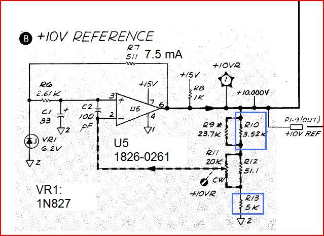
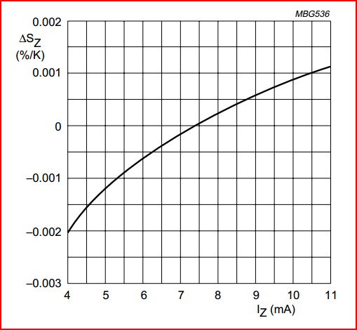
It is run at exactly 7.44 mA, using the 10 V reference to set the diode current – to minimize the temperature coefficient. See this diagram from the 1N827 datasheet:
Seems that after 34 years of aging, it is perfectly stable now.
Back-up of the internal EPROMs (4x 4 kbyte!) stored – just in case they fade out over time.
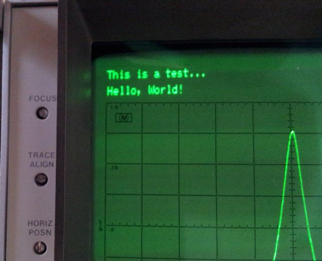
Last step – test of the GPIB functions – and, no issues at all.
Writing to the machine:
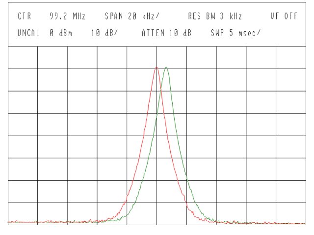
And receiving plot data back (two signals, close to 100 MHz, -10 dB):
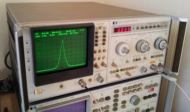
At its final place, for now, on top of a 3585A – total of almost 200 pounds of test equipment. Hope the bench won’t cave in.