
Like with most PLL build, there a quite a few things that can go wrong – the result: a lot of phase noise. For the current setup, all precautions had been taken to avoid bad surprises – low noise supplies, well-proven loop filter amplifier, low noise DAC, adequate cables. And, phase lock was quickly achieved (see last post).
For more detailed analysis, both the 160 MHz and the 21.4 MHz IF signals of the MSR-904A are fed to analyzers. For the 160 MHz, to a RTL SDR stick, just for the rough picture, and the 21.4 MHz, to a 3585A analyzer. The 3585A has very low noise, ideally suited to look at phase noise, except if you are working the ultra low noise segment.
Initial finding – phase noise is down at about 60 dBc at >10 kHz offset, dropping off as expected, but the close-in noise is really bad. Close in noise often related to the phase detector, or the reference. Substituting the 10 MHz reference from the EIP545A by a really low noise HP 10 MHz OCXO didn’t change much. So to high noise level must be connected to phase detector.
With the detector set to 1.25 MHz (:8 reference divider), there we can gain quite a few dB of noise supression, by increasing the detector frequency (within limits, doubling the detector frequency lowers the associated noise contribution by about 3 dB). And, even more, we can check out the reference doubler, which is a build-in feature of the ADF4157. With the doubler in use, it needs to be ensured that the duty cycle of the reference is close to 50%, but this is ensured by the OCXO anyway.
The ADF4157 can handle phase detector frequencies of up to 32 MHz, no issue at all with 20 MHz. The only downside – more fractional-N spurs – channel spacing for integer only dividers is now 160 MHz, rather than 10 MHz….
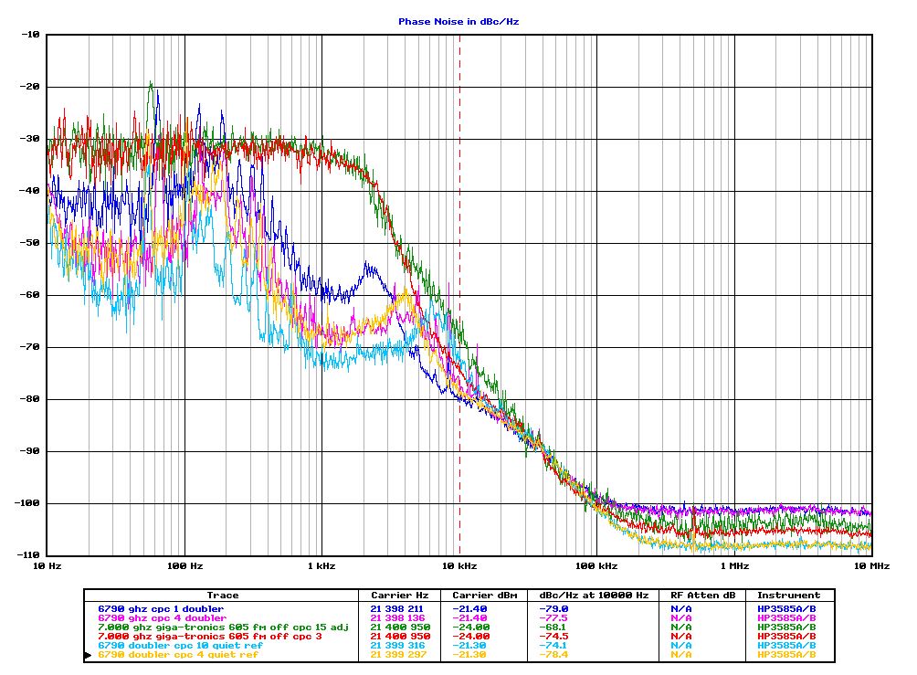
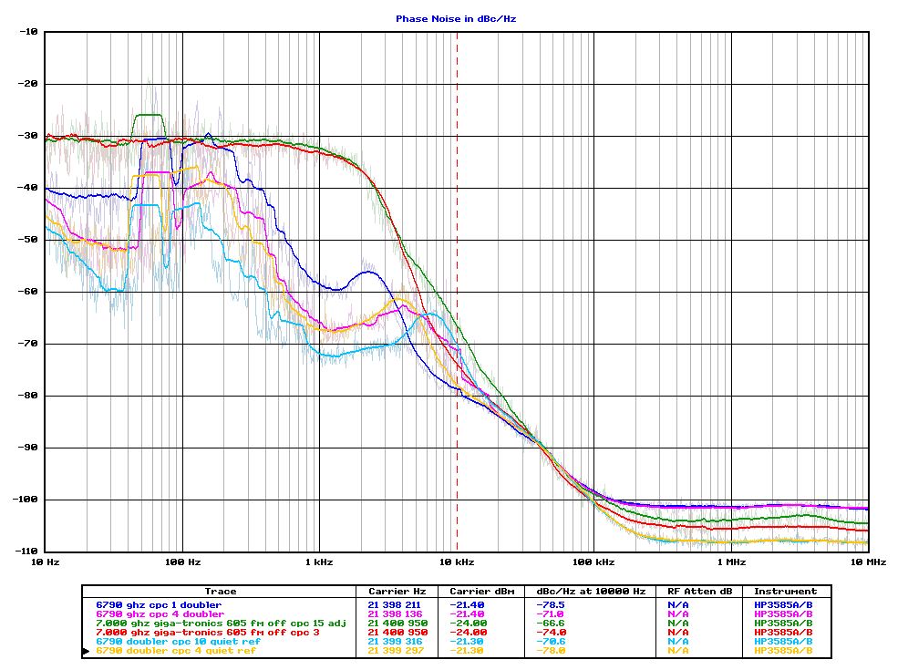
Red and green traces – you can see, the PLL is completely detector noise saturated within the bandwidth.
Other traces – all with a phase detector frequency of 20 MHz – and at different charge pump currents (CPC). A CPC of 15 corresponds to a 5 mA current. This has direct impact on the phase loop cut-off frequency. There is some peaking, at 2 kHz (dark blue trace, CPC 1), and at about 7 kHz, light blue trace, CPC 10.
Comparing the yellow and magenta traces – these differ by the 10 MHz reference signal source only (yellow uses an HP 10811 OXCO, magenta uses the EIP 545A build-in reference which is pretty stable, but rather noisy). In the curent setup, both references yield very similar results – accordingly, the noise within the PLL bandwidth is dominated by the PLL cirucit itself, and the phase detector, not the reference source.
There are some mains-related spurs at 60 and 180 Hz, but these might just be due to the temporary cabling and lack of a proper case. The circuit is fully exposed, tranformers closeby, etc. For the final setup, all cables will need to be as short as possible, especially for the pretune voltage (which is about 2 MHz per Volt – 2 kHz noise for 1 mV!).
Credits go to KE5FX for the great PN.EXE phase noise measurement tool, invaluable for any such work!