
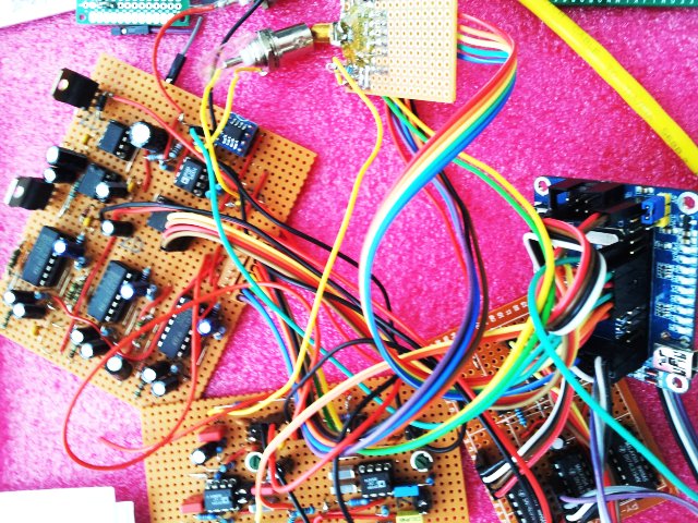
Comming back to an earlier project, the frequency stabilizers/PLL controls for the Micro-Tel 1295 receiver (2 pcs, one for through, and one for reflected power), and the Micro-Tel SG-811 generator (0.01-18 GHz).
The setup has been working well, but it is an awful mess of cables, as a result of the development process.
Now is a good time to finalize the circuit, and to put it into a nice case.
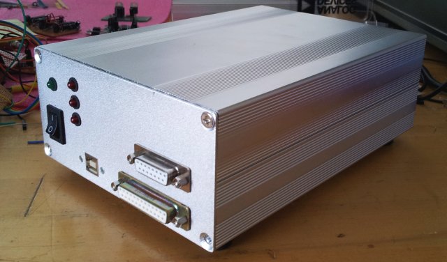
This is the front panel – the back panel has numerous BNC connectors, for the “PLL Phase Lock” voltage, and the “Frequency Control”, i.e., coarse tune voltage. The latter voltages, 3x 0-10 Volts, are generated by a DAC board, which is now ready and tested. Not a thing of beauty, but it works, and no reason to assemble another one just to clean things up a bit.
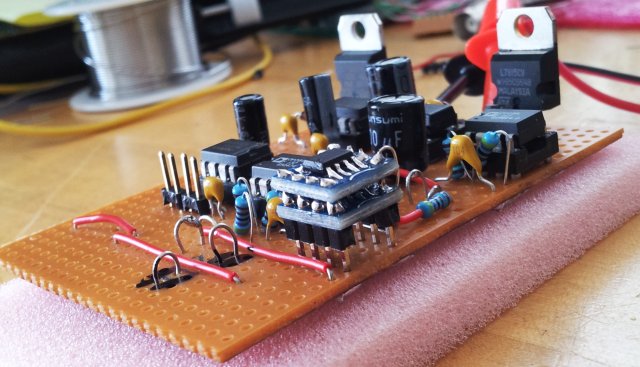
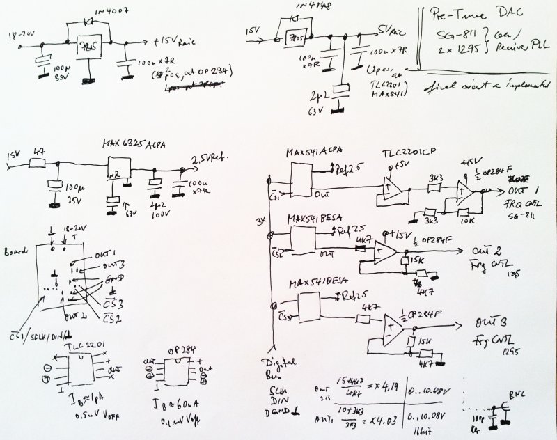
The circuit is reasonably straightforward, a 2.5 V precision reference is used, and three MAX541 16 bit DACs, followed by OP284 amplifier to convert the signal to the 0-10 V range.
The MAX541, it’s a really great part, full 16 bits, +-1 bit integral nonlinearity, and very stable over temperature and time. Highly recommended for any precision application.
One of the channels has an additional TLC2201 opamp, which is there more for historic reasons than for anything else.
The PLLs use three ADF41020 18 GHz chips, following the approach discussed earlier. This will give 100 kHz frequency resolution, which is more than sufficient for the intended purpose of measuring gain/attenuation and SWR over the full range of microwave frequencies up to 18 GHz, or 40 GHz, if no SWR measurement is required.
The 10 MHz reference circuit has also been completed, and is working well, converting a 10 MHz input signal (of more or less arbitray shape and amplitude) to 3x 10 MHz REF signals for the ADF41020, and two 5 MHz outputs, for the 1295 receivers, just in case I need to work with external downconversion-the 5 MHz signal is only affecting the 0.01-2 GHz range of frequencies. Well, why not having everything phase locked, if we can.
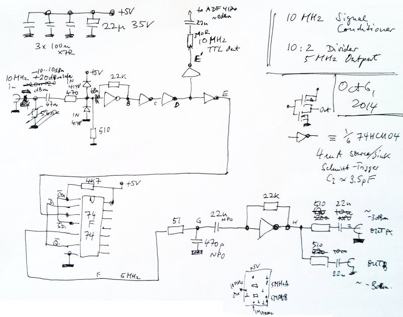
The 10 MHz circuit has been modified slighly, to accept 1 kOhm impedance 10 MHz input signals, which are rather common for instrumentation purposes. Some caps and protection circuitry has been added, output levels are just about 0 dBm. No need to go to stronger signals, it will only cause spurious response, and other trouble, because shielding inside of the PLL case won’t be very strong.
Some remaining work, before we can call this project complete:
(1) A power supply regulator, +5, +3, +3 (Vp low noise), +15, +20 supply has been build, but need to be mounted to the case, for heat sinking. This will need to wait for a few weeks, need to wait for some travel to Germany coming up, where the metal working machinery resides.
(2) Digital interface and cables for band control of the SG-811, and the two 1295s are complete, just need to be mounted and tested.
(3) Relais control module needs to be designed and build – there are two 18 GHz transfer switches (one is needed for basic functionality, a second one for the various unexpected test configurations). The transfer switches are HP 8763B, see earlier post. These are wonderfully precise and repeatable, albeit, list price is about USD 1k, each.
(4) Need to route the two serial signals (dB reading, signal strength) from the Micro-Tel 1295 to the ATMega32L, which only one USART input – no problem, because this is all TTL-level USART signals, but need to get a multiplexer/a few NAND gates to set this up. Currently, only one 1295 can be recorded at a time, which means, either gain or SWR measurement.
(5) Sure, the software, both firmware and instrument control software will need to be refined and consolidated. All PLL calculations and adjustments are done within the ATMega32L, still there is a need for a more convenient user interface than just command line.
… to be continued!