
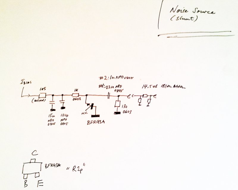
So far, we have mainly been discussing series type noise sources, i.e., noise sources where neither anode nor cathode are connected to ground. Another common design is shown here – the shunt configuration (one port of the noise generation element grounded).
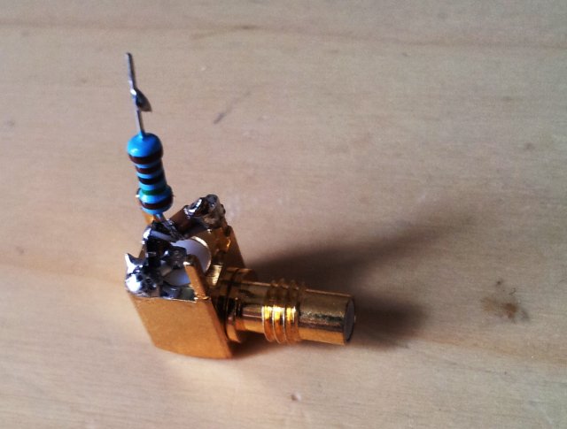
The assembly, more or less just a little blob of solder with a few tiny parts inside… mostly, 0603 SMD format. The output attenuator (not shown) is a 14.5 dB(!), 18 GHz coaxial attenuator.
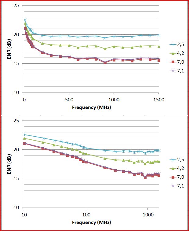
Some quick measurements, at bias currents of 2.5, 5 and 7 mA…. still, there seems to be a lot of 1/f noise (increase of noise power at lower frequencies). This is model #1, with a 22 nF capacitor (see schematic)
Don’t really see any advantage over the series variant of the noise source. But will test further.
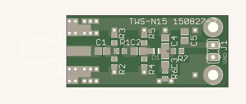
…Progress on another front, ordered a set of PCBs – they can be used for various noise source configurations. Not yet a “prototype”, but need to see what kind of GHz performance is available from such design, and how reproducible it is. No current source yet on this PCB – will add later, or on a separate board – to limit shielding to the RF section.
Hi,
I also played around with several types of noise sources. I used diodes, transistors, incandescent lamps, vacuum tube, LEDs and photodiodes as well as LFSRs.
Interested ?
https://electronicprojectsforfun.wordpress.com/making-noise/
Very interesting! Will check it out. Also experimented with some Russian noise diodes here with good success.
Hi Simon,
what kind of Russian Diodes did you use ?
The pretty popular 2d2s. At least it is also producing some light, not only noise!
Yeah, right. But dont overdo it with the light, or it will turn into a roman candle and burn out after a very short time 🙂
It could also be that a red hot anode could also emit some electrons, maybe altering noise output. I need to check.
Hey, this looks very interesting. I am looking for a noise source for 5GHz-6GHz. Do you think that this will work?
Probably yes, but it won’t have 15 ENR noise power unless you adjust the attenuator. In any case, I would suggest a design using a coaxial attenuator rather than the discrete SMD resistor type at these frequencies to get reasonable return loss. I had good results in the past by soldering an noise transistor directly to a good quality SMD connector, and using a fixed attenuator. The current source will stay the same. Good transistors are BFR93A or similar. Drive currents about 8-12 mA.
Thank you very much for your response. I am pretty new in RF so I have a lot of reading up to do. By “SMA connector” you mean something like an U.FL connector?
I was thinking about using an SMA connector, since this is what I use throughout the System.
And you just solder the transistor to the connector? No other components? This is probably a stupid question but at the moment a lot of the RF schematics look a bit like magic to me. I guess I should simply start experimenting.
Thanks for the hint with the coaxial attenuator. I guess I will order some BFR93A transistors and start experimenting.
Again, thank you for your Time.
SMA connector, I mean a simple SMA print solder type connector, so that you can connect a fixed SMA attenuator, say, 6 dB attenuation, to it.
On the other side, the pin, you need to add a small capacitor like 100 pF, SMD 0603, and then a RF transistor. See http://www.simonsdialogs.com/wp-content/uploads/2015/05/simple-rf-noise-source.jpg
Ah alright, just wanted to double check I did not miss-understand.
You have been very helpful – thank you again.
Grüsse aus AT.