
Quite honestly, I don’t like these compact fluorescent lamps (CFLs) too much. They save energy, maybe, but the light produced is not really appealing, and in the long winters here, some extra heat produced by an ordinary light bulb is much appreciated anyway.
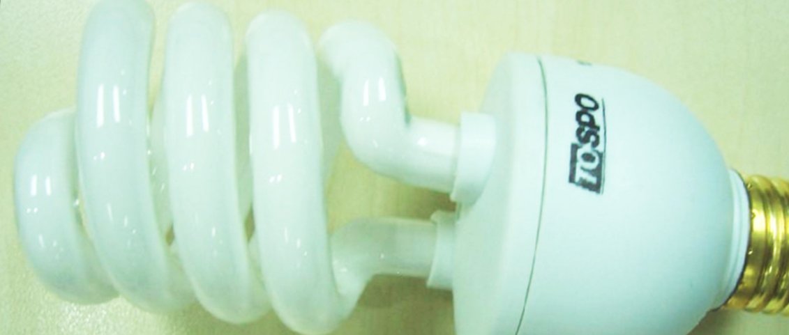
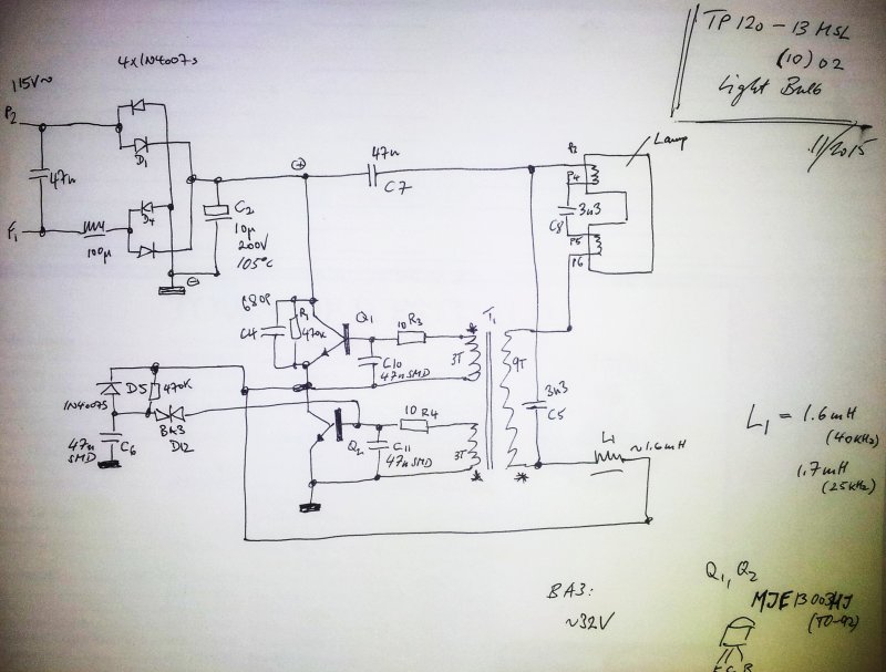
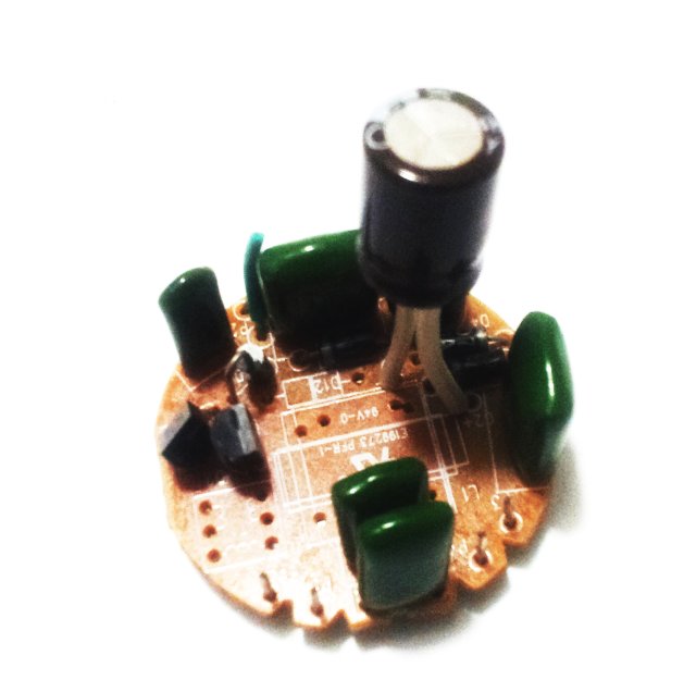
Having a few defective CFLs around, I could not resist to open one up and check inside. That’s the schematic.
More can be found at other sites, this is quite comprehensive: CFL Schematics (LabKit).
The circuit uses a rather small ring core transformer, two primaries, for feedback, 3 turns each, and a secondary, 9 turns. Two transistors MJE 13003 (in TO-92 package) are arranged to form an oscillator circuit. These transistors can handle 600-700 V no problem. The DIAC (BA3) forms the starter circuit, giving a first few pulses to the oscillator, when the lamp is still high-impendance (prior to ignition). Once the lamp has started, the D5 diode will disengage the start-up circuit.
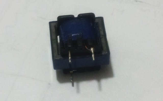
The transformer:
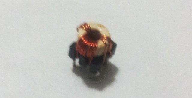
Below, wrapped in blue tape, and with an E-E ferrite core, that’s the choke, about 1.6 mH inductance, which is part of the lamp’s resonant tank (along with C3, C5, and the secondary transformer – and C7, which will play a minor role, because of its comparatively large value).
la resistencia de 470K debe ir conectada al positivo para que pueda cargarse el capacitor C6