
Recently, I have moved a U2508 milling/drilling machine to my Ludwigshafen workshop (from the remote workshop, where there is more space for heavy machinery). It’s a really good machine, slim, but very well built and useful for all kinds of drilling and milling work. It has an automatic feed in in one direction, and the dials are usually quite accurate.
Still, it will be a great advantage of time saving and some accuracy improvement to add a linear scale, at least in the manually-moving direction, so I can mill shoulders and similar features to a very high level of precision and repeatability.
Also the quill will get an electronic readout – but this will be covered later.
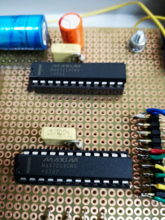
Luckily, I had a simple readout around, dating back to 2007, based on an ATmega8515, with some logic, and MAX7219 display drivers.
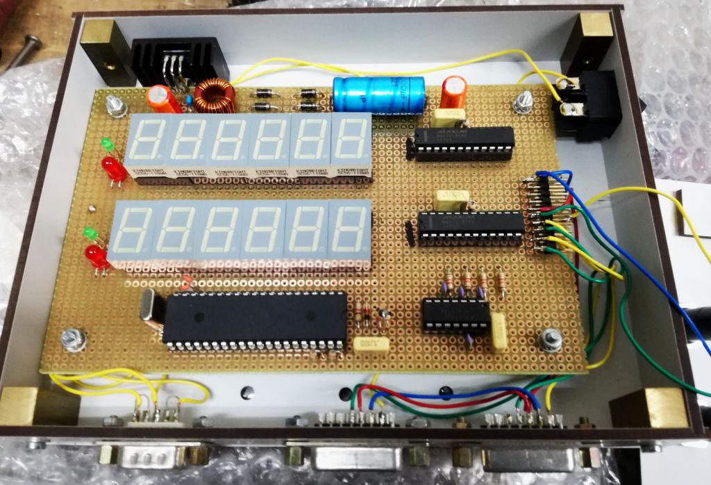
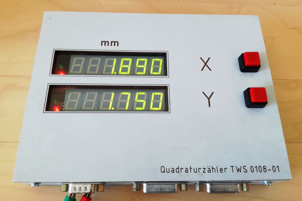
The case was made from melamine composite boards, these are oil and grease resistant – excellent for workshop use.
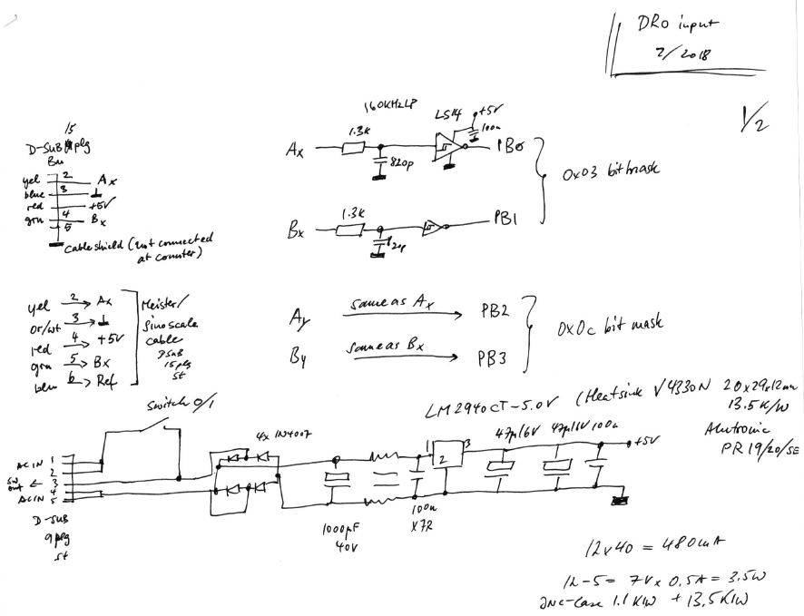
Here, the schematic of the input section. The sampling frequency of the counter is about 62.5 kHz, so the TTL signals from the glass scale first pass through a ~160 kHz low pass filter, and are then squared up by Schmitt triggers, 74LS14.
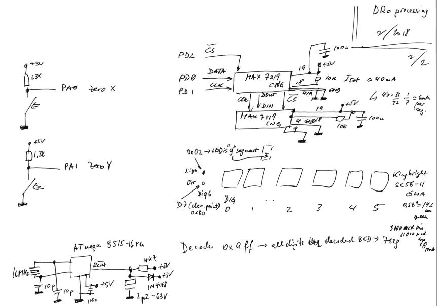
The main processor is running at 16 MHz, and very few extra parts are needed to drive the LED 7-segment displays, using two MAX7219 in chain configuration. The LED segment displays are much preferred for workshop and DRO use, because speed and clarity is everything for this application, and nothing can really replace the good old LED 7-segment displays here.
The power section, note that the regulator will need a heatsink of about 10~15 K/W capacity
– the unit is drawing up to 0.5 Amps at 5 Volts.

The input section…
The drivers…
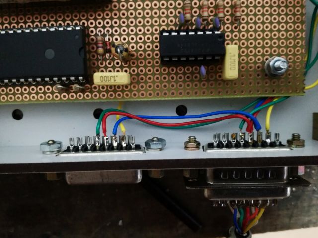
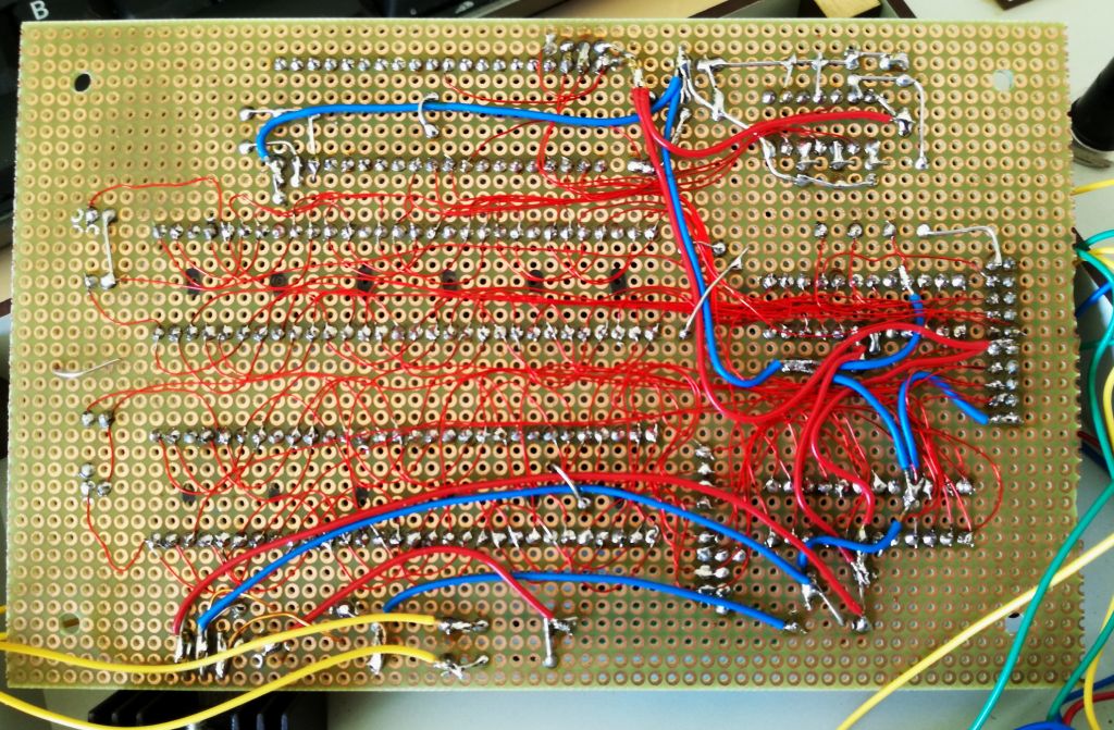
The wiring, all quickly soldered together with some copper wire.
The code – it uses a gray code approach with continuous sampling of the A/B inputs. This approach is easily coded, and has very deterministic timing, and noise immunity. Any errors found (like, if both lines change state within on sampling cycle) will be indicated by a red LED.
Now, I only need to mount the glass scale (found one that fits in may parts collection…), and replace the “minus” LED (a 3 mm LED) with a minus bar-shaped LED, just for the better looks.
Note that the software has provisions for a matrix key-pad, but for the present application, the “zero” buttons are all that is needed.