
With most of the 3580A functions working again, we still need to fix the digital display. Essentially, the 3580A uses a digital scope circuit, similar to those use in digital oscilloscopes of the 70s.
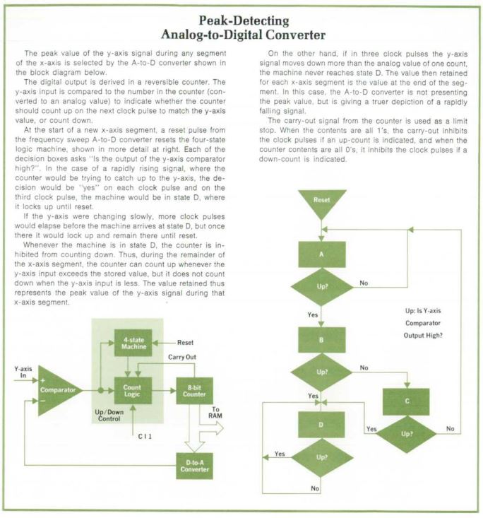
First, some study of the ADC. The 1973 HP Journal has all the details, it is successive approximation, peak detecting ADC.
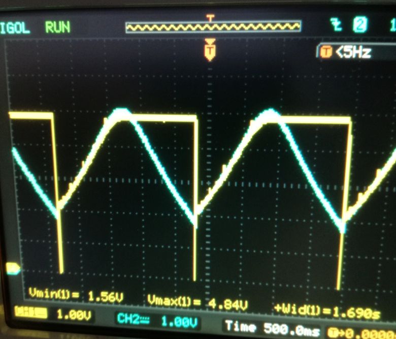
Checking the input to the digital display board, blue trace, and the comparator/approximator input to the ADC, yellow. Seems something is wrong with the ADC ciruit, or it’s timing-counter control systems.
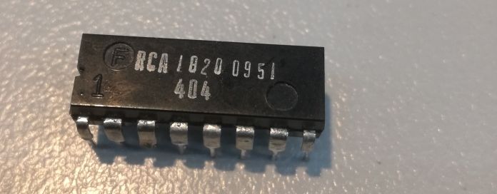
After considerable checking and probing, I found the issue, a dead 4019 CMOS, 4×2 multiplexer. Replaced it with a “new” part, taking great care to avoid any static discharge to the board.
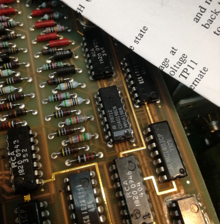
The dead part, it is almost a historic piece! 1974, only a few year after the introduction of CMOS circuits by RCA!
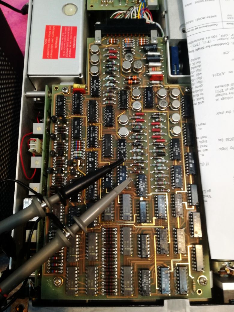
That’s the full board. Multiplayer construction. Plenty of precision resistors that are needed for the ADC circuit.
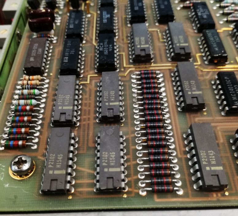
Another working antique part – the 2102 S-RAM, Intel, 1 kbit per circuit. 8 pieces – a total of 1 kbyte of SRAM!
Working display…

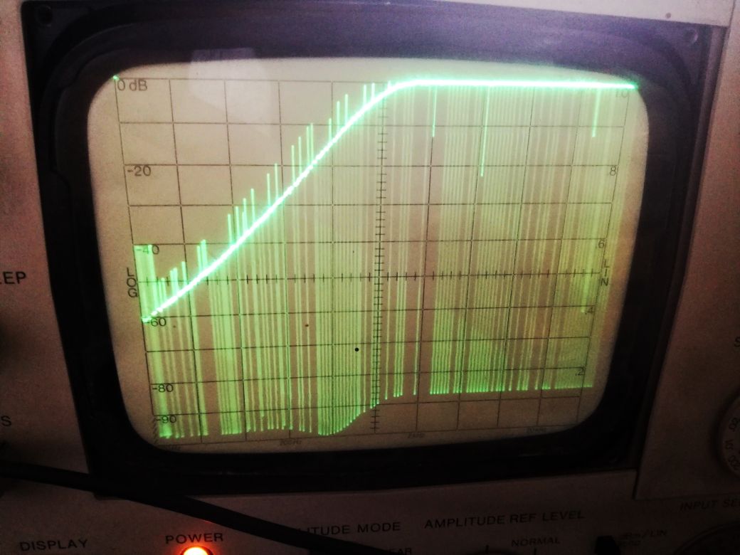
10 kHz reference display… Great!
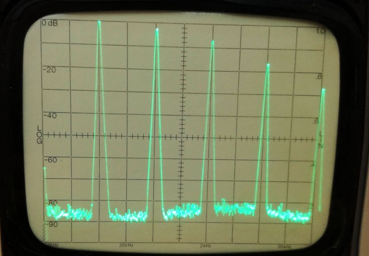
Even the log scale scan is working.

One tip – put all the screws and parts in a box, and check that it is empty afterwards. So many instrumented I receive here in the workshop are missing some screws or other parts.
![]()