
In a recent post,HP 4191A, I have introduced a 4191A with defective power supply. In the meantime, a spare power supply regulator assembly arrived, and the repairs of the originally fitted, defective supply have been completed.
First, some research into the HP p/n 1826-0043 Opamp, which is considered to be a LM307 comparable part. But what is acutally inside the can? Let’s crack it open.
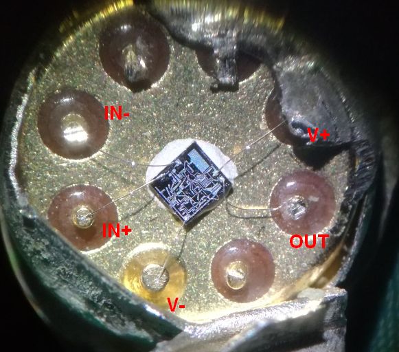
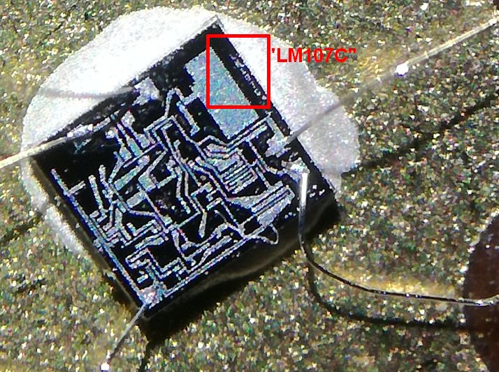
The die has a small marking, reading “LM107C”. The LM107 is very similar to the LM307, except for a wider temperature range, and somewhat extended power supply limits. In the current application, we can safely drop in LM307N opamps. It is also clearly visible that there are no bonds for external frequency compensation (like for the LM301).
The replacement power transistors have been discussed in the earlier post, and now all has been cleaned and new heat conducting grease added.
![]()
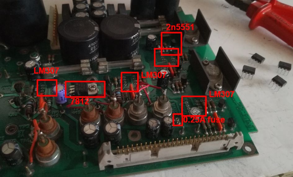
All the replaced parts marked, after all, I should have also replaced the fuses and fuse holds which show signs of corrosion and bad contact.
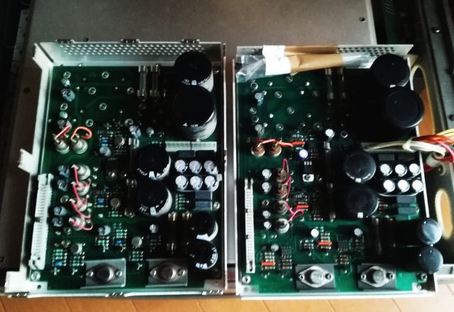
A quick test, on the 4191A, left hand side is the working spare, the right hand side, the repaired original supply. I didn’t connect it to the 4191A board, but just to the transformer to confirm the basic working condition without putting the 4191A to any dangers – the repaired supply with but just a spare, and probably it will never be needed… at least not for this unit.
There were no other defects with the 4191A, and now some tests with the 4191A working instrument. It is essentially a very precise one-port vector network analyzer, with a thermostated reflection bridge and some other features that make it suitable for component measurements. There are some (expensive) HP test fixtures, but essentially, you don’t need these because most of the components will need to be tested on some custom boards, or directly soldered to a test connector, to avoid parasitic effects at the frequencies of interest. I just used a set of SMA flange-type connectors.
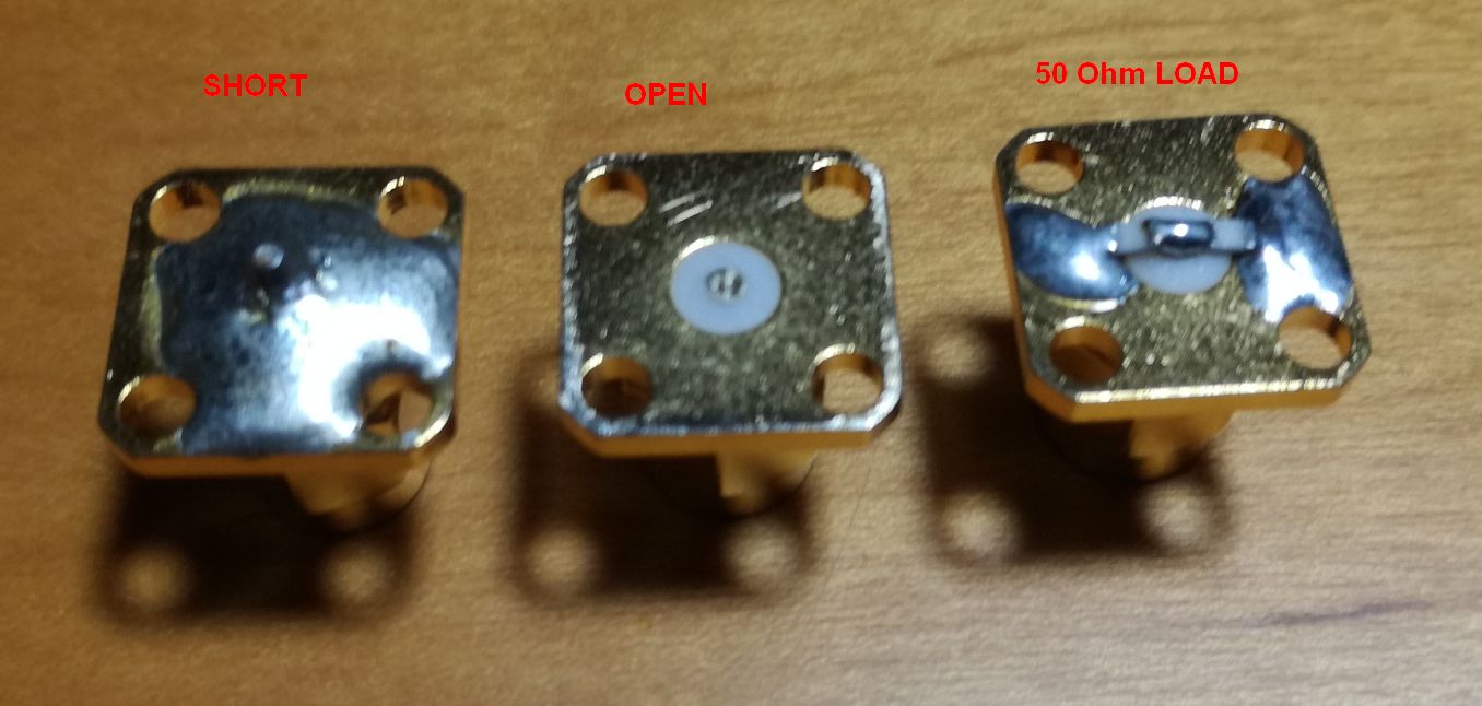
First some standards were fabricated – a short, by applying a generous amount of solder the connector to completely short it, an open, by cutting off the center pin and machining it flat (maybe need to add a cap or other structure later, to avoid any parasitic capacities, for now, during calibration, you just need to keep the hand away (and any other ground planes). The load 50 Ohms – from two 100 Ohms SMS resistors in parallel.
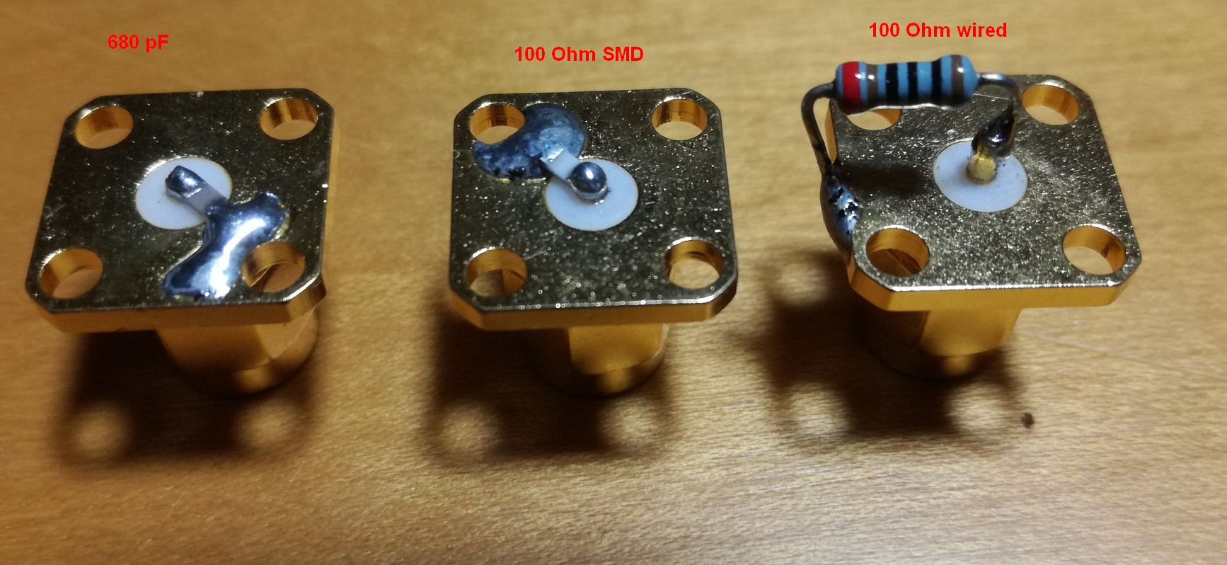
Some test objects, a 680 pF SMD 0805 capacitor (NP0), a 100 Ohm SMD 0805 resistor, and a wired 100 Ohm metal film transistor.
The test itself, run with some excellent Excel software (by a certain Harry Percival) and Zplots (by Dan Maguire, AC6LA) via GPIB bus.
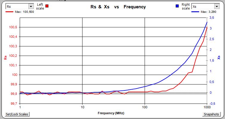
The 100 Ohm SMD resistor, it has pretty good performance out to 1 GHz.
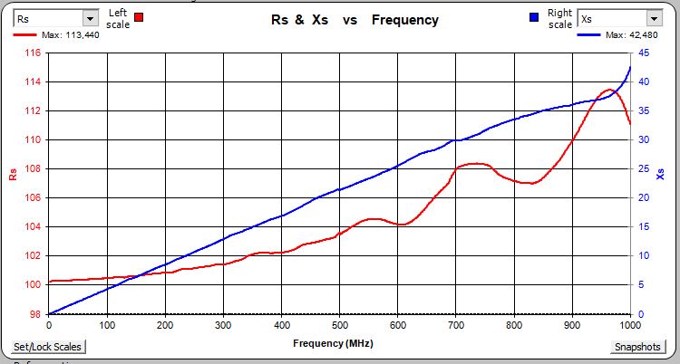
The wired transistor, inductance is adding to the parasitic behavior.
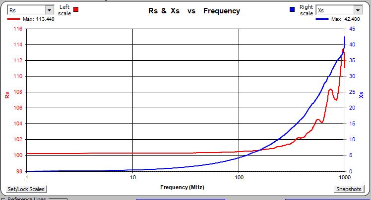
… same in linear frequency scale.
The 680 pF capacitor.

Also did some drift checks, over 10 hours (after about 2 hours of warm up), I could not find any detectable drift of the Z values, so the instrument seems very stable at least with reference to the stability of the 50 ohms load measurement.
Hello Simon, looks like you have a good working example of a 4191a, it’s nice to see vintage machine back in service, HP equipment from this era was built to last, and I appreciate the mention re the excel software, though if I was to write it now it would be in python, the VBA within excel is limited, especially the GUI which can’t be locked down.
Harry ei8hvb
Your Excel tool works just fine, it worked right out of the box. Sure it would be great to have a python or C version (I was just about about to write a small C based test library when I came accross your software). I am now thinking how to build a little heater/Peltier to characterize capacitors at various temperatures.
I don’t have access to my 4191A just now, it’s in storage, but I do recall a couple of anomalies.
On my machine there was a step in the response at about 11.5Mhz, I think it’s from additional gain used below 11.5Mhz and the switching point can be seen in the response, also the two front end hybrid circuits were prone to problems where the adhesive on some components broke down, on some hybrids you might see evidence that they have been opened. The replacement for these machines were expensive and there was a lot of effort to keep them in service. Good luck with the setup, looking forward to reading how u get on. PS it might have been 13.5Mhz, can’t recall for sure.