
Working through the guts of the 4192A, I tried to operate the A8 assembly, which has several +-15 V isolated power supplies (for floating voltages, etc.), and a +-40 V bias supply, set by a pretty cerdip DAC.
Basically, the assembly consists of a set of switched power converters, converting the +-15 V input, to isolated +-15 V output. Running at about 900 kHz to 1 MHz.
The assembly is double shielded, to interference with the impedance measurements. It has a set of coils and capacitors, a number of parts! Definitely not a cheap unit to build at the time.

The issue – when connecting it to the 4192a power supply, it loads down the +-15 V rails, and the power supply assembly A7 of the 4192a soon goes into shut-down. Not a good sign.
Analyzed the circuit by touch, almost burning my finger – the two main switching transistors of the 4th supply are glowing hot!
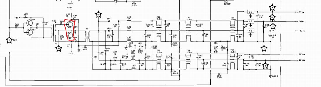
Did some measurements, and the transistors, as well as two capacitors are dead. The other capacitors, I removed them because you never know, and better to fix it now than later.
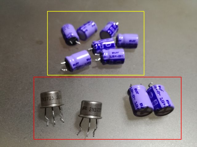
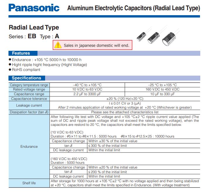
Interestingly, the capacitors HP selected were 85°C rated, I decided on some Panasonic EB series, 105°C rated, low ESR-long lifetime caps. Hope these will last another 30 years of occasional service.
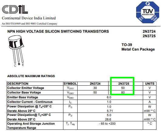
The transistors – difficult to find good substitutes. I believe some other reasonably high current NPN fast transistors like SS9050 or similar would work, but I don’t want to take chances and found some new-old-stock 2N3725 on eBay. Only it will take a while for these to arrive in Japan!
For the time being, I desoldered the working transistors of the #3 supply, to get the #4 supply going for the tests.
Surprisingly, one of the transformers has a damaged pot core, K5 ferrite, difficult to get. Strangely, there were no loose pieces inside the shields, and no traces of earlier repairs. Can it be that HP fitted a slightly defective transformer? But as the unit is working and outputting plenty of power, the core should be good enough.
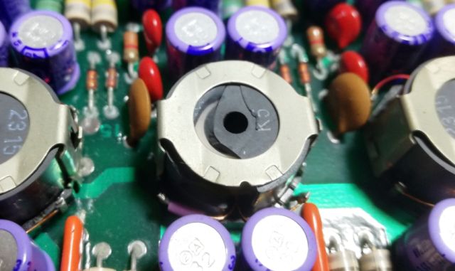
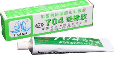
To fix it, or at least make sure that it is not rattling or desintegrating any further, we have a choice of epoxy glue, super glue, or silicone. I decided on the latter, a 704 type head conductive silicone. It is available really, cheap, and it is good stuff, because it can be removed later without destroying the coil, should I ever come across some K5 pot cores.
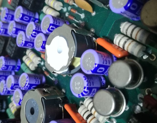
All fixed and stable.
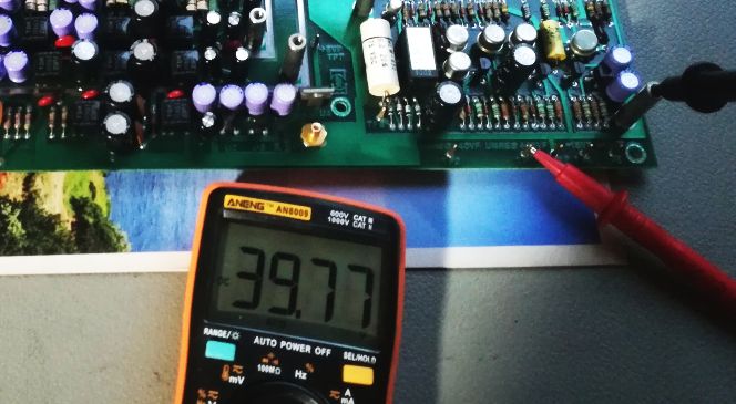
A quick test – powering from a current limited lab supply (about 80 mA on 5 V, about 0.11 Amps on +15 and -15 V with no load are needed for the A8) to avoid destruction.
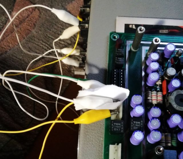
Fortunately, the A8 assy is working again. I didn’t test the DAC, but no reason to believe it would not work.
Now just waiting on on the 2n3725A transistors, and then, it can be all put togethers with many screws and pieces of shielding metal.