
Recently, we have to work with many PLL designs, mostly the frontends, based on ADF41020, ADF5002, ADF4157 and similar circuits, including their programming. So I decided to design a little board that can flexibly interface to all these circuits, and provide enough power.
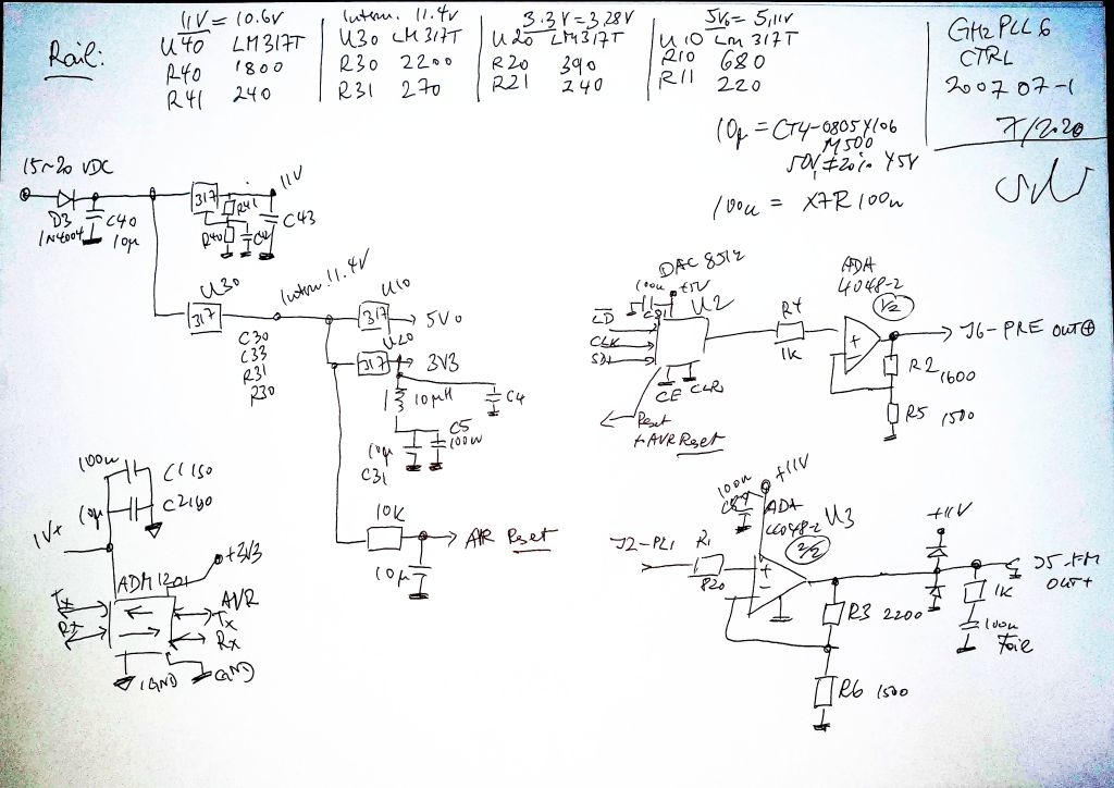
(1) Power supply to allow 10 V full scale output, 5V supply, 3.3V (or 3V) design. Noise should be low and flat without any discontinuities or peaks.
(2) A pretune circuit with 12 bit monotonous tunable voltage, scaleable to 0..10 Volts to control the main coil current drive of YTOs.
(3) A PLL loop amp to adjust the working range of the PLL FM tune (PLL circuit may provide 0-5 V, but need to have a driver to translate to, say 0-10 V). Used an ADA4048-2 low noise rail-to-rail opamp. These are reliable, and can tolerate somewhat capacitive loads like long cables.
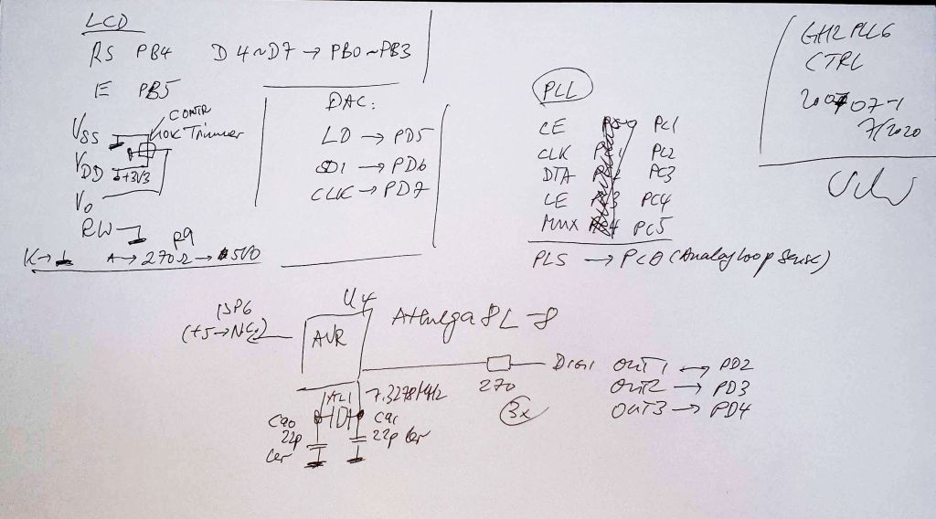
(4) An isolated RS232 (TTL level) interface that can work at any reasonable baud rate (7.3278 MHz will do the trick as MCU clock).
(5) Easily in-circuit programmable, we use a common ATMEGA8L-8 MCU.
(6) Some status LEDs. Say, 3 LEDs.
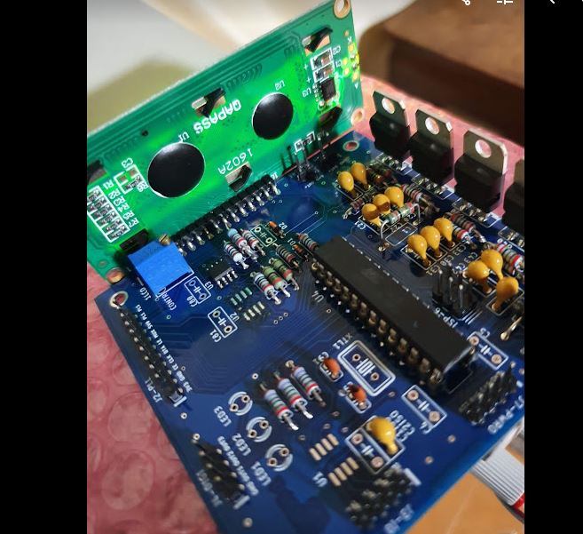
After not too long, came up with this design and had it manufactured as boards at 40 eurocents a piece(!).
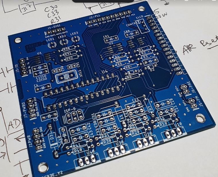
The schematics, they are a bit rough, but if you need more detail, let me know. All fairly standard. The regulators are good old LM317T, with 10 uF bypass caps. This gives reasonably low noise, and we can operate this without special cooling over a wide range of input voltages (15-20 VDC). Current consumption incl. LCD is about 40 mA.
The LCD, any common LCD board will do. I use a 1602A 2×16 character.
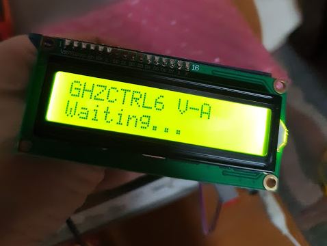
After some fiddling around, it is working temporarily. Programmed the ATMEGA8 just fine.
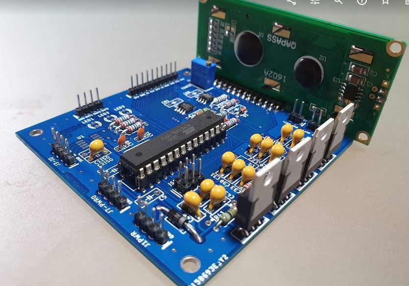
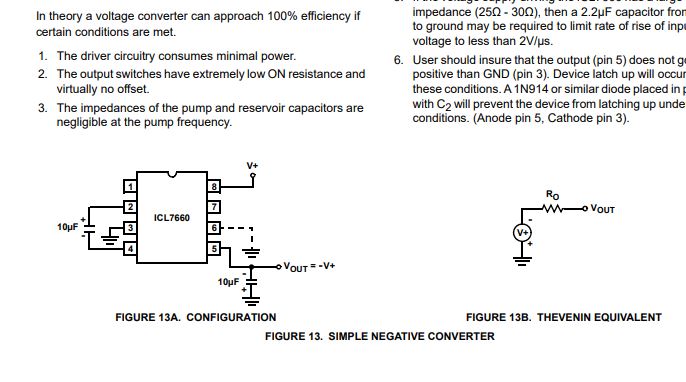
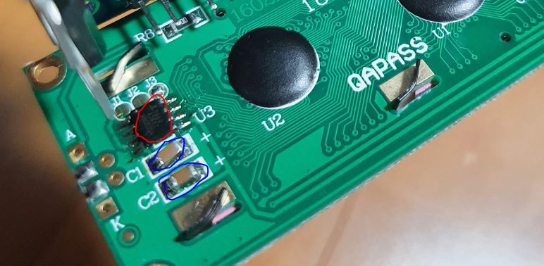
The LCD, it took some in-circuit repairs because after a short time of operation the contrast faded away. Note that this is a 3.3 V LCD that has an ICL7660 to convert +3.3 V to -3 V. But not with this module, just getting about -0.2 V. After replacing the ICL7660, it turned out to be a shorted capacitor (tested 10 Ohm!).
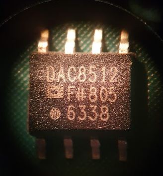
With things working pretty well, soldered in the SMD DAC, a DAC8512 (DAC7761 also works with same pinout and performance). But rather than the expensive parts for production sourced from major distributors, resorted to some low price parts purchased in sets of 10 pcs, and at hand here in my temporary Japanese workshop. Did do much D to A conversion, but rather shorting the inputs to almost ground and consuming lots of power. Not good. Some forensics showed that these are certainly not DAC8512, but something else (with diodes and circuits inside) marked as such. Strangely, from the same reel/cut tape, there are Philippines and China made parts, all a bit scratched and strangely smelling like fake. The laser marking are all the same.

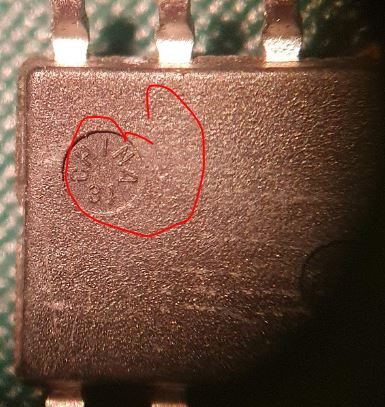
Markings on the Philippines parts:
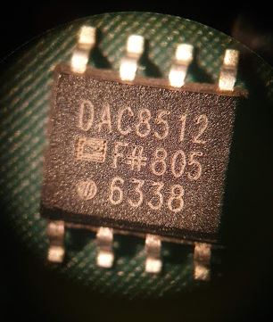
Markings on the China parts:
I have some genuine parts back in Germany but no picture handy currently. Well, I ordered some more DACs to get this to work, but won’t be an issue, the amplifier is working just fine.
Ah.. a board suitable to drive YTO is sure interesting. I have some Watkins-Johnson YTO and YTF that came from a Loral radar warning receiver. 1970s vintage stuff, but on powering one up I was greeted with a nice signal on the spectrum analyser.
Wilko