All posts by Simon

HP 8569B (8565A) Spectrum Analyzer: curing the knob disease

Having seen quite a few of the 8569A, 8569B, and 8565A analyzers in the shop recently, once common issue are the controls. The 3-knob operation is one of the features that makes these long-established machines still desirable for today’s work, in particular, for general test and troubleshooting in the microwave region, up to 22 GHz, and above. At the same time, these knobs were made of plastic, and they age – most of they show cracks, which will sooner or later require difficult repair. In the current case, I am dealing with the unit described earlier, it is a 8569B, and someone had fit a 8565A control pad – all of the knobs more or less cracked and useless – I might use their remains to fix upcoming instruments.

So, what do to? Well, decided to go for a rigorous approach, and provide completely new knobs. These use a coaxial design, with 1/4″ outer shaft, and 1/8″ inner shaft. For the small controls, just ordered a few Augat/Alco knobs, which are quite sturdy and easy to mount.

8569b augat alco knob

The large knobs, I custom machined back home in the main workshop, using my little CNC lathe (kind of an overkill) – they are made from POM/Delrin plastic, with some brass inserts, and 4-40 set screws. The knobs are knurled at the outside – one turned out a bit black, because I didn’t clean the tool properly… fair enough.

8569b large knobs

The only downside – there are no markings on the knobs, like for the originals, but such markings aren’t really needed for the 8569B which has a full on-screen display of all settings. Also the ‘lock’ positions for coupled BW-Span still works!

8569b new knobs detail

8569b new knobs mounted

All in all, I’m pretty happy with this repair, estimated useful life of the new knobs – 30 years, and replacements can be made, as we go. But maybe, by then, the unit might be really obsolete, although that’s the thing I am least sure about!

HP 3326A Two Channel Synthesizer: a engineering mystery, and a fuse mystery

…coming back to the 3326A repair, a slight mystery remains – at one time in the past the over-voltage protection circuit must have been triggered, destroying not only the SCR, but also damaging some quite large traces on the board. Typically, the SCR is just switched on for a few milliseconds, before the mains fuse will blow, with no damage of any trace. Typically, these HP devices are well engineered, so there is only a small chance that they didn’t design the system right, to the extend that power would be provided to the board for any length of time even with the over voltage protection circuit triggered.

3326a over volt protection hot trace

Now, the 3326A has passed a 24 hour run-in and multiple power cycles, time for the final safety check which I perform on any instrument repaired, like, checking the ground resistance, checking the isolation resistance, checking the mains fuse rating, etc.

THE FUSE. SOMEONE MUST HAVE BEEN FULLY CRAZY, AND PUT IN A 20 AMP FUSE!!!

3326a fuse 20 amp
That’s why the over voltage circuit didn’t work, and presented a fair risk of fire and instrument damage, of an instrument, sold at over USD 10k, 1990 dollars.

The fuse rating – 3 Amp, normal blow.
3326a fuse rating

And a big warning sign, hard to overlook.
3326a fuse warning

But what is a normal blow fuse? In the US, fuses are actually rated by the manufacturers, and standardization is well above the level of fusing time, etc. – two types are typically sold, ‘Slow Blow’, and ‘Fast Acting’. Slow blow fuses are easily idenfied, they either have the wire wound around a ceramic core, or are filled with sand.

Found this document, related to ‘normal blow’ – as it turns out, these fuses are actually identical in rating to the typcial ‘Fast Acting’ fuses that I have in stock here.
normal blow fuse

agc fuse
Well, there might still be some tiny difference of the original, HP branded ‘normal blow’ fuse, but test shows that a regular 3 Amp AGC ‘Fast Acting’ fuse is working perfectly find. So for the time being, we can just consider ‘Normal Blow’ and ‘Fast Acting’ fuses to be identical. How easy would be the world, if all things were build according to common, well-established standards. At least, for the fuses.

HPAK (HP Agilent Keysight) 3326A Two Channel Synthesizer: power supply trouble

Should you ever send in any instruments for repair, please ensure it is properly packaged!
3326a packaging
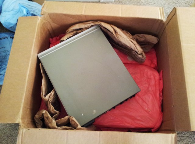
This defective 3326A dual channel synthesizer arrived with no major transport damage, but only due to luck, not due to proper packaging.

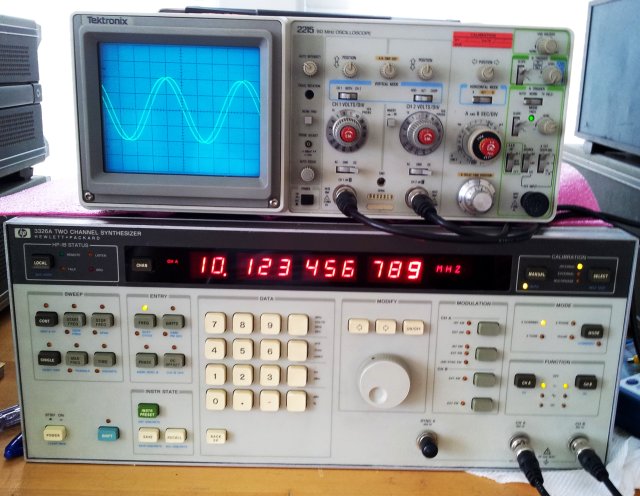
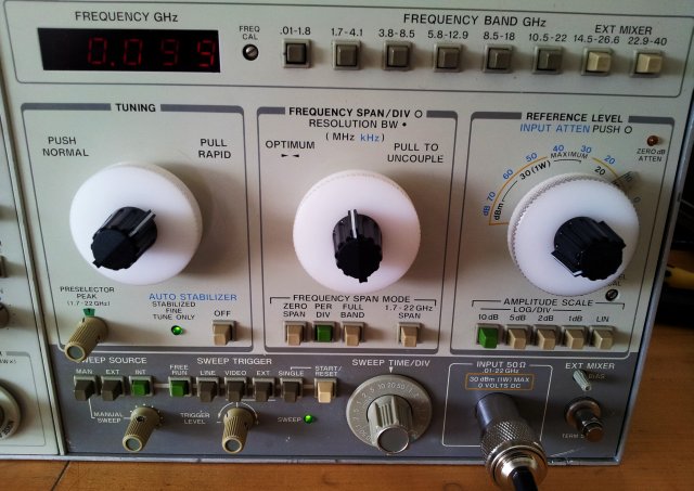
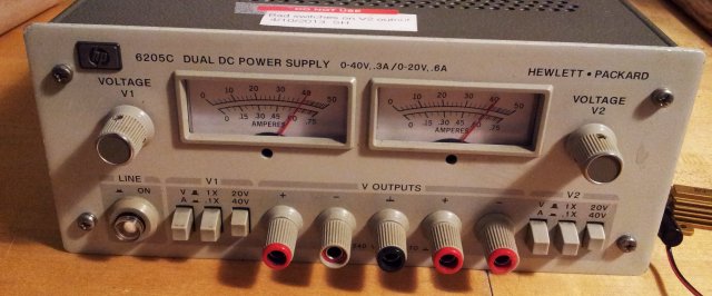
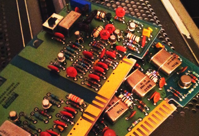
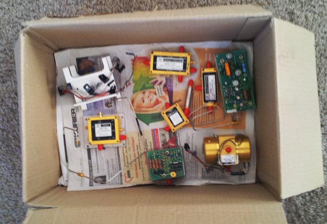
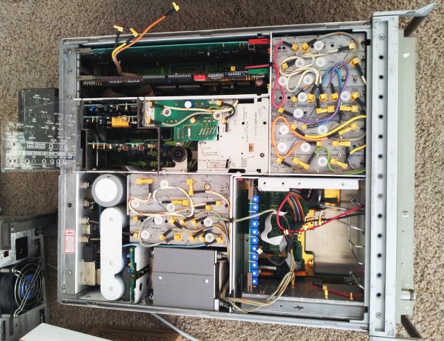
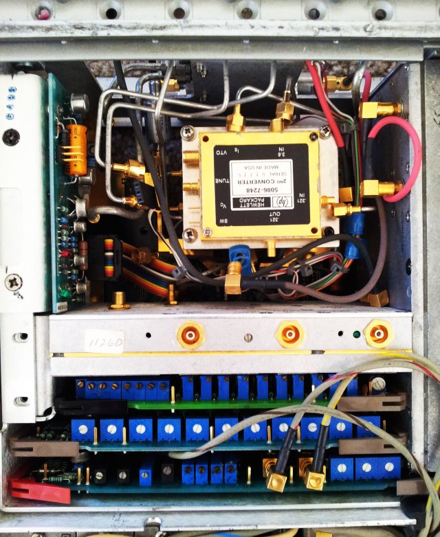
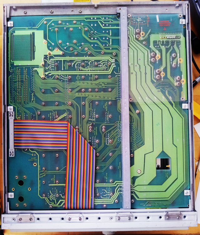
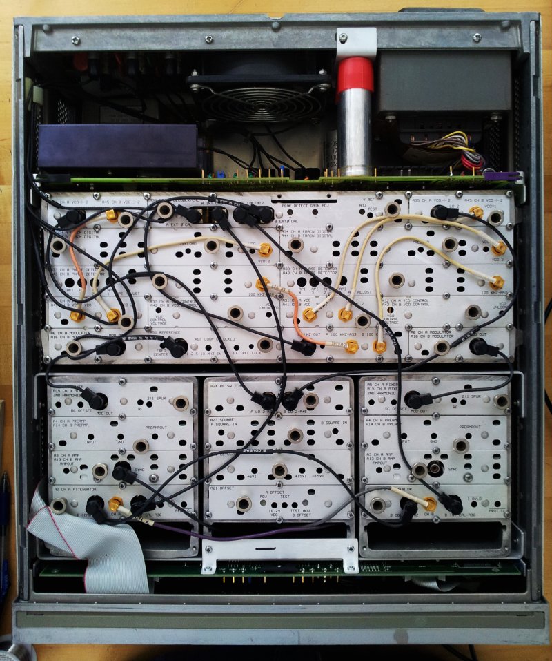
First, let’s open up the top panel, and have a look inside. There are two complete synthesizers in the box, similar to the massively popular 3325A design. The synthesizers can be combined, for various two-tone operation modes, phase-shift and PWR modes, two-tone sweep sources, etc. This makes the 3326A a very hand instrument to test all kinds of mixers, receivers, amplifiers.

3326a top view

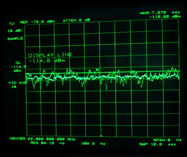
The outputs are extremely precisely frequency settable, down to 10-6 Hz in the kHz region, and 10-3 in the MHz region… that’s 1 part in 10+9, so you can simulate small oscillator drifts – the frequency stability of the current unit is excellent, it features an option 001 OCXO, +-10-7 per months drift.
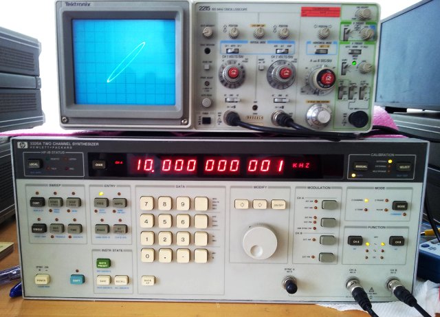
The 3326A is also great sources for modulated signals, having all kinds of internal and external modulation sources, including phase modulation. This makes it very useful for PLL characterization, phase detector characterization, or similar tasks.

Well, in priciple. The current unit arrived in dead condition. Plugged it in – a bit of smoke, and bad smell, that’s it.
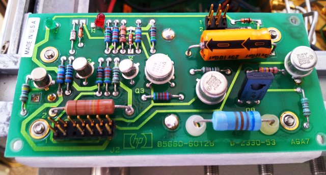
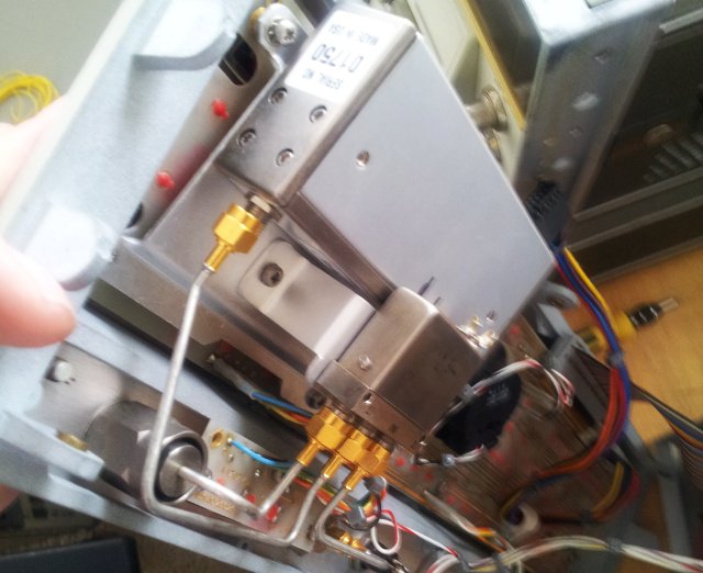
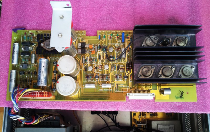
The faulty assembly: the 03326-66570 power supply.
Another issue: No service manual!!! There are 100s of HP service manuals around, but none of the 3326A!!! Very disappointing – if you have one, PLEASE LET ME KNOW! Your help will be highly appreciated!

3326a  03326-66570 pwr supply

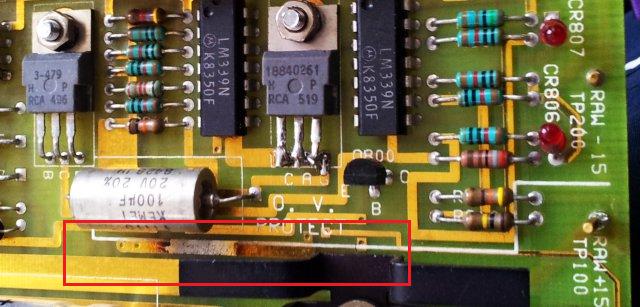
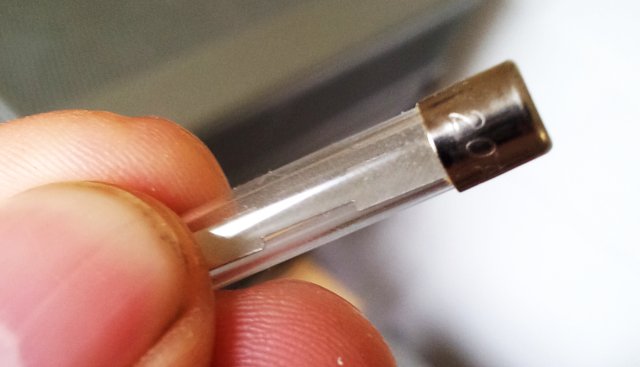
Someone must have tried to fix it before, because a few parts are missing – a screw, attaching the capacitors to the case, and a SCR (aka, thyristor), of the over-voltage protection circuit, CR800.

First fix – the ‘smoking’ capacitor, C706. A 100 nF ceramic cap, at the input of the rectifier – actually, running with about 50 V AC, and a cap, rated at 50 Volts… no idea why HP was doing this – typically, they employ a large safety margin, when designing the circuits. Not it this case, and not to the benefit of reliability.

3326a pwr supply c706 defect

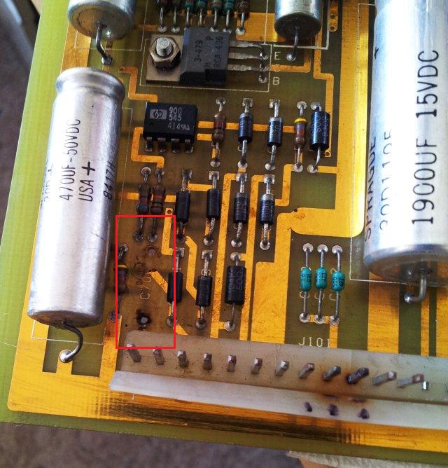
Unfortunately, the cap heated up the traces, and damaged the board – so I removed to loose traces, cleaned it up, and soldered the a replacement cap to the bottom of the board.

The protection circuit – the board was missing the CR800 SCR when received – I can’t find anything wrong with the voltage sense circuits, formed around two LM339 comparators. But there are burnt traces that show that high current must have been flowing throught the SCR at some occasion in the past, possibly due to an over-voltage condition on some of the rails. And the former owner of the device didn’t bother to put a new SCR back in.

3326a over voltage protection 1884-0261 scr

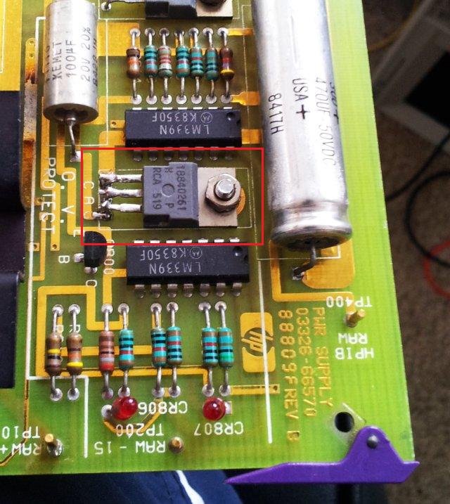
Fair enough, put a spare 1884-0261 back in, a 100 V, 4 Amp on-state RMS current. Will replace it later, either once I found out the original part number from the service manual, or once I get hold of a 100 V, 16+ Amp, TO220 device (which rest back in the main workshop, in Germany, while I have to get the 3326A going here at the US East Coast).

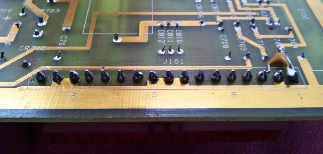
While inspecting the power supply, also noticed that the J101 connector – the main connector to the transformer – had several bad solder joints, seems the plating has come off the pins, making bad contact, even leading to head being generated. Resoldered the pins with big blobs of solder, not my usual style, but should work fine here to distribute the current more evenly.
3326a pwr j101 connector soldered

Now, the moment of truth…. switched it on, and, all rails are up (you can use the little jumper on the board to operate the supply outside the slot – don’t destroy your instrument by putting back in an untested power supply assembly!).
3326a test
…it works! Seems we have won, and still some years to go before this instrument will turn into a paperweight, or, well, a doorstop.

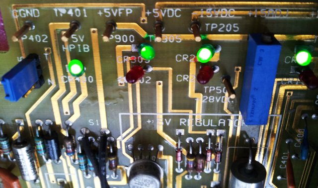
As usual after repair, now, running it for a few hours, switching it on and off a few times – checking the stabilty of the output. Not so good news. Sometimes, instabilities show up, and after a few power cycles, it doesn’t come on any more. Then, it comes on again – an intermittent fault! Never good!
Good advice, in case of intermittent faults – let them develop into permanent faults, and in this case, watch the ‘power good’ LEDs of the various rails.

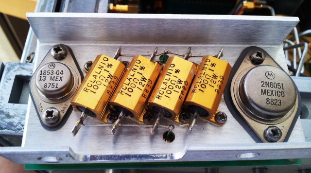
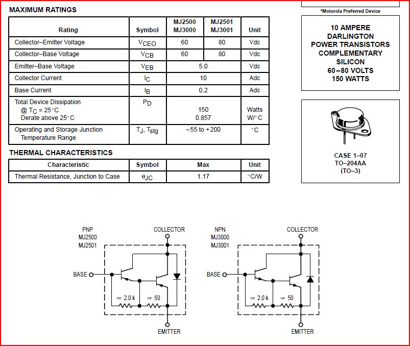
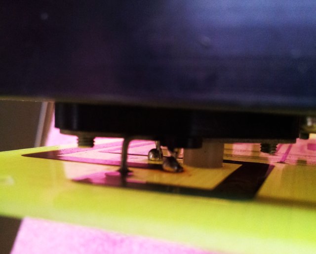
After a bit of probing, knocking, knocking, pushing – found the issue to reside with the 5 V rail. Even without the service manual, a few tests of the voltage regulator shows that the regulator working, what is not working, is the series pass transistor, a HP 1854-0618. This is a re-branded Motorola MJ3000.

3326a 1854-0618 transistor 5 volt rail

3326a mj3000 transistor

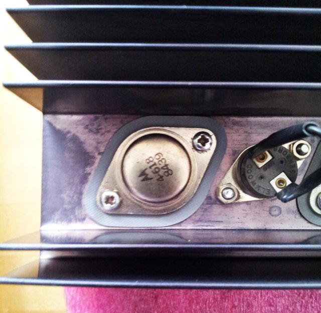
A dead transistor that has intermittent function, very strange. Look at the way it is mounted – using a pcb-mount TO-3 socket. Let’s remove the transistor, and check it out…

3326a to-3 contact

3326a transistor oxidized pin

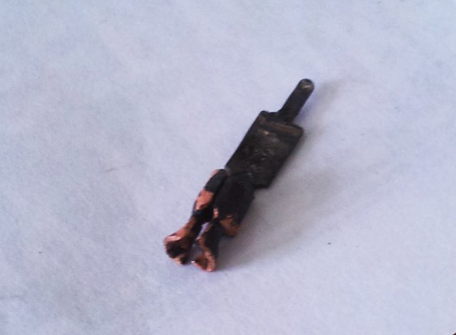
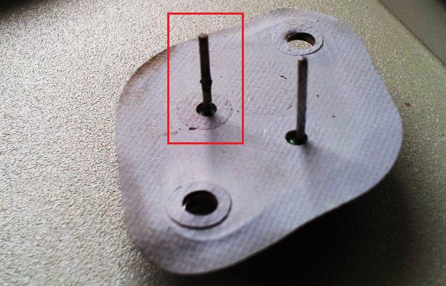
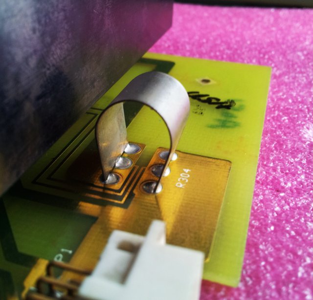
Now, things are clear – the 5 V rail is quite high current, and the pin-socket combination (for the emitter pin) just isn’t made for it, well, at least not after 30 years of service, oxidation, and so on. One day, it must have heated up quite a bit, judging from the state of the contact. No way to fix this by just cleaning it up – the contact is all soft, and won’t provide a low resistance path. So, I removed it alltogether, and soldered in the pin, using some tin plated copper wire.

3326a to-3 print mount

Also noticed some discoloration of the via at the emitter pin – the heat caused some damaged, but not too much, and also here, added a large blob of solder, to ensure good contact both sides of the via.

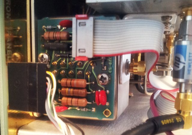
Talking about the obvious engineering weaknesses of the power supply, also some good things – it actually has several protection circuits, all rails are protected by heavy Zeners (which will short when overloaded), plus the active monitoring-SCR circuit.

3326a power supply monitor

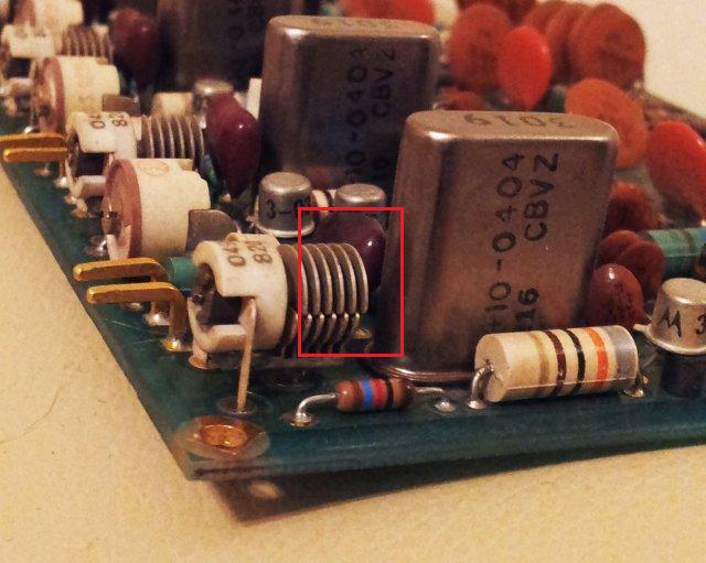
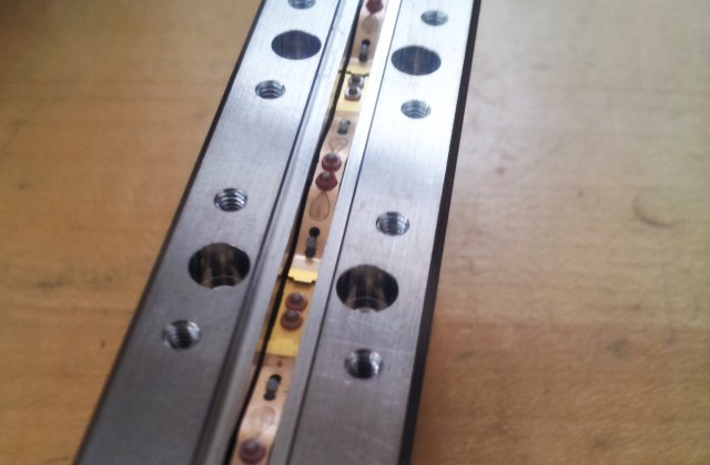
For the 5 V rail, even the current is monitored, by this rather fancy shunt.

3326a pwr supply shunt 5 v rail

Gave it another few hours of run-in, and numberous power cycles, still, all is working just fine.

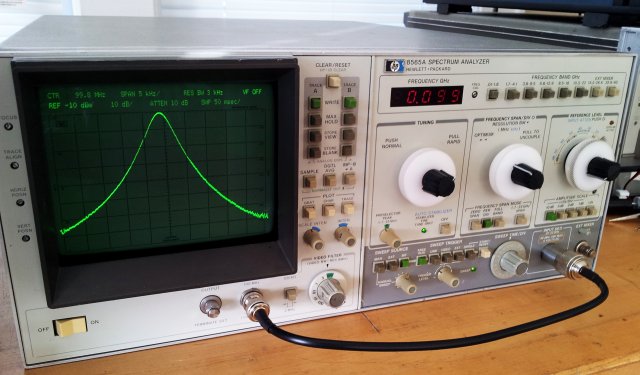
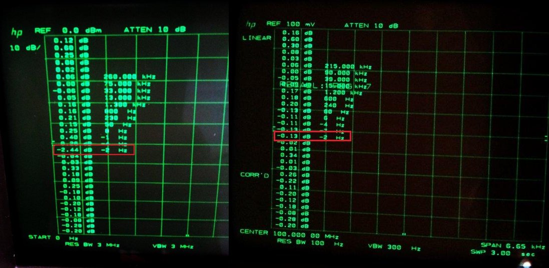
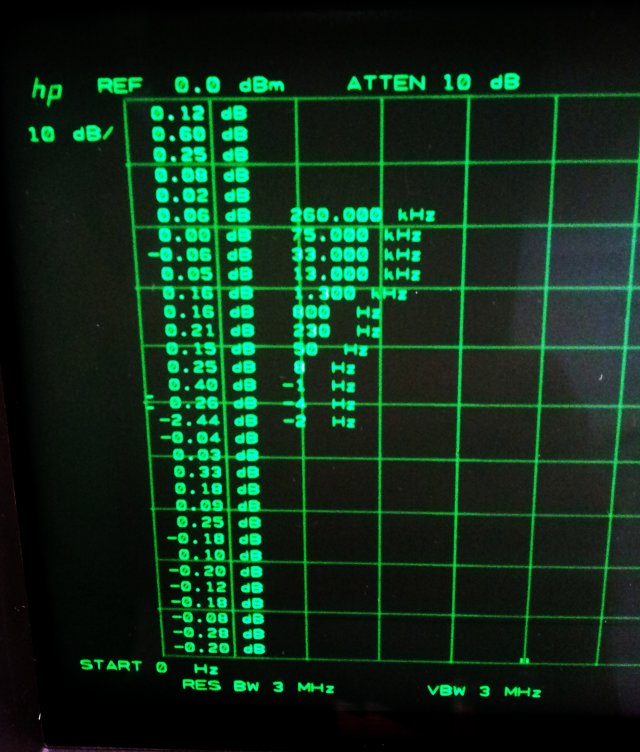
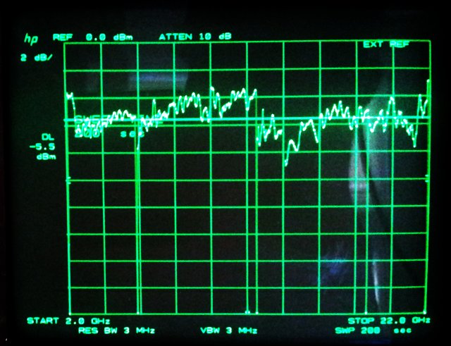
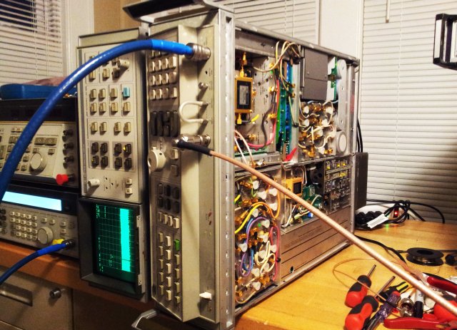
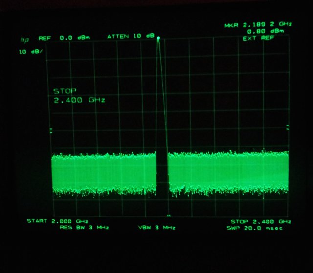
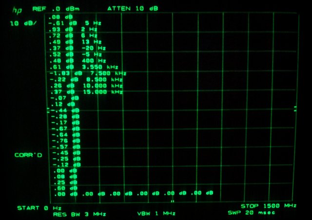
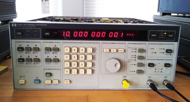
Now, check out what it can do:
3326a working

3326a 10 khz xy

HPAK (HP Agilent Keysight) 6205C Dual DC Power Supply: a mechanical fix

Today, a package arrived, containing, a defective 6205C dual power supply. This model is capable of 0-20 V, at 0.6 Amps, or 0-40 V, at 0.3 Amps.

6205c front

The ranges, as well as the meter indications (V or A, x1 or x10 scale) are selectable by two groups of pushbutton switches, and someone figured out earlier that the switches for the V2 output are defective….

6205c bad switches

… well, not quite. The switches work, but they don’t stay pushed in. A mechanical failure?

6205c top view

Fortunately, it is quite clear what had happened. Someone dropped the instrument, and the front panel was hit – bending it inwards, reducing the gap from the switches to the circuit board. With insufficient room to work, the switches appear inoperative.

6205c panel

To fix this, no soldering iron is needed, just a hammer, and a piece of wood, to get the front panel back in shape and aligned.

6205c tools

6205c connectors

The front terminals are a bit damaged, but they work, and I will have a look around for a few spares (these are 1510-0091 binding post – let me know, if you have one around), or try to fix them by some custom-made red plastic inserts – this will have to wait for the next winter!

HP 8566B (85662A) Spectrum Analyzer: fixing the 10 Hz issue, A4A7 3 MHz filter assy

The 8566B/8568B analyzer both use the 85662A spectrum analyzer display section, which is not just a display but also takes care of the IF processing. For the 10 Hz to 1 kHz bandwidths, a 5 pole xtal filter is used. A rather delicate assembly that dates back the the earlier analyzers, 8565A, in somewhat modified form. As a side note, HP had a strong tendency to utilized time proven circuits, some of them, over periods of 20 to 30 years… it helps with the repairs, once you get used to a certain assembly, the same pattern is repeating in multiple instruments. One of the examples it the A4A7 assembly of the 85662A (p/n 85662-60004). It is a rather ingenious design, and is critical for the 10 Hz resolution which makes the 8566B/8566B units so useful to resolve close-in spurs, like mains spurs.

The unit currently on my bench showed issues in the 10 Hz bandwidth – not enough gain. First, I assumed it to be an alignment issue, and spent quite a while re-adjusting the circuit. To no avail (well, it helped to improve the passband shape, which is now perfectly symmetrical again).
Almost wanted to give up. But not quite.

Checked the gain of the A4A7 with one of the stages, at a time, bypassed by a substitution circuit, a 47 n capacitor, in series with a 2.8 ohms resistor (see earlier entry). And, quite surprisingly, the gain of the 10 Hz bandwidth increased dramatically when shorting the 5th of the xtal poles.

8566b peaking cap

After careful inspection, notice the peaking cap. It is at its lowest value – this might be the issue – each of the poles has at least 3 adjustments: center, symmetry, peaking, and 2 of the poles, also a gain adjustment…. Maybe, the 5th stage (which is working at all the other bandwidths), is just not set to peak!!

85662-60004 a4a7 assy 5th pole

The 68 p capacitor, it is a factory selected component, and 68-82 p is the allowable range. This assembly had a 82 p fitted, but only at the 5th stage… well, just a few pF too much.

Where to get a 68 p cap (a silver mica…) now, one big ocean away from the well-assorted stock back home in the main workshop? Well, always good to have some old, spare HP boards at hand:
8566b scrap board
…one of them now is missing a 68 p cap….

After some re-tuning, running the calibration routine, look at the result, before and after:
8566b corr coeff before and after repair
…there are the missing 2 dB. Problem solved!

HP 8566B Spectrum Analyzer: YTO/YTX tuning, flatness adjustment, and an OCXO

The 8566B I am dealing with here as parts from at least three units, so no wonder that the YTO/YTX drivers are all completely out of adjustment. So much that the LO sometimes locks on an incorrect multiple of the reference, or that it doesn’t lock at all.

Well, the adjustments are all well described in the manuals, rather straightforward.

8566b corr coeff
The amplitude offset at 10 Hz, a bit more than I want it to be, but this is related to the A4A7 assy of the 85662A, not to the 8566B itself.

8568b flatness adjusted
Might still tweak it a little bit, when all repairs are complete, but for now, a quite satisfactory result.

The OCXO, it is mounted in a set of 3 rubber isolators, here are the rough dimensions, if you want to fit a custom OCXO….
0960-0477-1 osc 49-61c dimensions

8566b 0960-0477-1 osc 49-61C 10 mhz ocxo

From the service manual – there are at least two versions of the 8566B, one using the HP 10811, and the other, using an Ovenaire OSC 49-61C.
8566b a22 assy ocxo

As far as I know, the oscillators have more or less the same performance level, but the connectors on the motherboard are different (still carrying the same voltages – the 10811 has small add-on regular board, 5062-1909), and there may be also differences in the holding brackets.
5062-1909 10811-60111 board
Notice the different plug! I have a spare 8568B motherboard around that supports this connector style.

One of the many test results, the 22 GHz noise floor.
8566b baseline noise 22 ghz

Not bad at all, about -118 dBm. Also checked the power line spurs and the noise characteristics, all considerably better than specified.
The only downside: total weight, of the 8568B: 112 lbs, and two strong fans.

HP 8566B Spectrum Analyzer: 2 partial units and some spare parts

This story starts with a set of rather valuable 8566B parts that I received for free a litte while ago:
8566b spare parts

A partial unit, stripped of of most of its RF parts, and missing some boards, and missing the OCXO.
8566b partial unit1

For a long time, I have been looking for another partial unit that can provide the missing boards, the OCXO, and some bits of hardware to complete the instrument. Not worried about the 85662A display units, because I have a perfectly working spare unit around, or could use the unit of the 8568B.
Finally, a unit showed up, also missing some boards and parts, but luckily, not the boards that I needed -except, also no attenuator, and no OCXO here.
8566b partial unit 2
8566b partial unit2

That’s the start, the empty space that is going to hold the RF treasures:
8566b empty space

The YTO assy, missing the YTO, and other bits.
8566b yto loop incomplete

This part, the 5086-7226, to do it fully justice, one would have to talk about it for a few hours. It is a not only gold plated inside and out, but HP used two kinds of solds, of different melting point, to assemble the inner workings in subsequent steps, without melting the already assembled parts….
8566b 5086-7226 YTF

Some more pictures – the YTF driver.
8566b ytf driver front
8566b yig driver back

The 1st and 2nd converter assy, ready for the semi rigid lines to be attached.
8566b 1st and 2nd converter

A high quality input relais and a band pass filter.
8566b input relais and bp filter

Well, unfortunatly, don’t have a spare 8566B/8568B OCXO around, and they go on xbay for no less then USD 50, often, no less then USD 100, that’s ridiculous.
May this unit, which is very low phase noise, very stable, from a HP 3585A analyzer, can be made fit? Ovenaire OSC 73-52.
8566b spare ocxo 0960-0465 ovenaire osc 73-52 10 mhz

After a LOT of fiddly work:
8568b assembly progress

8568b testing

A first signal!! Amazing! Frequency is off by 80/300 MHz – the unit will need a proper alignment, but the PLLs are all locked, which is a great start.
8566b a signal

And, the noise – the effect of harmonic mixing can be clearly seen, so the input stage and mixers seem to be all working!
8566b noise

More to come!

HP 8568B Spectrum Analyzer: a fair number of adjustments…. done.

Having the 8568B basically working again is great. Not so great were the correction coefficients, all seems to be a bit out of alignment.

Before alignment…. quite some deviations at 100 kHz, at the lower frequencies, and so on.
8568b corr coeff

This is the order of the coefficients:
8568Bcalerror

First, checked the log amp circuits, and all seems fine. No adjustment made.

The, some small tweeking of the A4A5 assy that controls the step gains.

Then, the major part, the xtal filters of board A4A7:
8568b a4a7 assy 85662-60004

Each of its crystals can be switched to 10-30-100-300-1kHz bandwidth, at virtually constant gain.
To do the alignment properly, each xtal has to be tuned separately, and some bypass networks are needed.

8568b bypass

8568b atx cable connector

The bypass network, a 2.8 Ohms resistor in series with a 47n ceramic cap – just use an old ATX power supply connector to get some suitable contacts. These come free of charge, whereas HP used to charge a dollar each, or more. Note that I did not have any 2.8 Ohms resistors at hand, so I used two 5R6 in parallel.

This is how it looks during the adjustment:
8568b a4a7 adjustment bypass

When all is done, the bandpass responses should be symmetrical, which they are, and the amplitude flat for all bandwidth. After running the calibration, these coefficients were found:
8568b final corr coeff

As you can see, it all looks great, except for the 10 Hz bandwidth. Carefully re-checked the aligment – 30-100-300-1000 is perfectly flat, but whatever I do, it seems A4A7 has extra loss when set to 10 Hz bandwidth. In priciple such situation can happen with misaligned crystals, or with some low-frequency issue of one of the amplifiers, which are rather unlikely. Maybe just some aged xtals? Will give it another try later, with flatness checks with some of the xtals bypassed, to see if the issue is caused by any particular of the stages. Found one of the 2.2 µF tantalum caps on the A4A7 to have high leakage current, replaced it, to no effect.

For now, it is good enough – specification at 10 Hz more relaxed anyway, and I never do 10 Hz bandwidth measurements without correction enabled, just considering that any modern analyzer basically relies on a good number of calibration and correction data stored somewhere in the instrument, and applied to all measurements.

HP 8568B Spectrum Analyzer: an amazing find, a few repairs, and a restored marvel of RF engineering

It appears that the US is a land of plenty when it comes to somewhat dated test equipment, otherwise, it would be hard to explain why someone would sell a 8568B analyzer, including a display unit, for just a few dollars. A great find!
In the as-received state, after removing the 8568B and the 85662A display unit from two huge boxes, it was starting up, but did not show any signal, and no annotations on the screen. The latter turned out to be a rather easy fix, a little defect in the intensity control circuit.

First step – adjusted all the CRT circuits, focus/intensity control circuits, and the analog/digital display scaling and stroke generator.
The CRT is of a quite amazing quality, not sure if it is the original CRT – it has a hand-written label sticking to it, which could indicate that it has been replaced at one point in time.

The major item, no signal (but a typical background noise trace) – this can be anything, but unless in cases of several neglect, it is hard to destroy the mixer or other hard to fix ciruits of the 8568B (typically, the attenuator, and the build-in limiter are absorbing any overload power).

Switching the input attenuator, some signal found at -70 dB attenuation! Strange, so there is something wrong with the attenuator.

Similar to the CRT, also the attenuator seems to have been replaced before:
8568b atten 5086-7815 70 db 24 v 4 ghz

8568b atten assy

Opening it up, with the necessary care, what a strange thing – the contacts are not making any contract… the screws indicate that someone has tried to fix it before, or maybe damaged these contact fingers, while trying to fix it.
8568b atten defective 2

This explains why only at the highest attenuation setting, there is a signal: the contacts work when pushed agains the 10-20-40 dB attenuator pads, but they don’t make contact with the pad bypass (“0 dB”).
8568b atten defective

Using some fine-tip tools, re-adjusted the contacts so that they close the by-pass of the attenuators.
8568b atten adjusted

Before re-assembly, make sure that there are no dust particles, and that the mating surfaces are perfectly clean. Best use a small, soft brush.
There is no need to over-tighten the screws. This attenator is the 4 GHz version, and not particularly critical. For the 22 GHz version, of same design, best check for SWR and insertion loss, and carefully tighten all screw with just enough torque to hold the assembly together.

Some checks, some adjustments – and the instrument passed the self-calibration with no issues. The coeffcients are not zero, but close enough, and cross check with a well-calibrated 8642B shows that the amplitude accuracy is perfectly fine, no issues with flatness, any of the attenuator settings, or when switching through the various bandwidths.
8568b corr coeff

Some of the other parts, the 1st LO – a YIG oscillator.
8568b yig

The reference, and OSC 49-61C, unfortunately, I can’t find any spec data for it, but appears to be a rather low phase noise oscillator, with more than adequate stability.
8568b ovenaire osc 49-61C

As a further note, should you be in the market for a 8568B or 8566B analyzer, make sure that it comes with the 85662-60093, 85662-60094 bus and interface cables.
8568b 85662-60094 85662-60093 cables
These cables don’t look like anything special, but are commonly sold for over USD 100 a piece, even in used condition. Often, the cables are lost when the instruments are put in storage, and auctioned later. Fortunatly, the current unit came with all the cables, even with a set of power cables!

A short glance on the main board, it is a marvel of engineering and a pleasure for the eye, all traces layed out by hand, fully gold plated, amazing quality and attention to detail. Might last another 100 years of 24/7 use.
8568b main board