All posts by Simon

Rong Hua (Bianhuan) “50 Watt” Travel Adapter: not enough iron, for this “wattage”

In interesting find, Made in China, a 50 Watt travel adapter.

autotrans sc-20c a

autotrans sc-21c

autotrans sc-21c receptacle

autotrans plug

This is used to convert 220 V (despite the US plug!) to 110 V – same device also seems to exist for conversion from 110 to 220 V.

The build quality is exactly what you expect for less than USD 7. A crude plastic case, two screws, no protection circuits or fuses, and a rather small transformer.

autotrans inside

Total weight of the transformer – about 140 g.

Looking at some transformer tables, this is about 6-10 VA (=”Watt”, if you wish) nominal size. For autotransformers like this, the nominal size needs to be converted to the actual power rating, by using the conversion ratio (voltage ratio). P_nominal=P_actual*(1-voltageratio). I.e., for a 220 to 110 Volts transformer, the ratio is 0.5, and a 10 VA nominal transformer can handle 20 VA if configured as an autotransformer.

Quite obviously, 20 VA is not 50 VA – please use these these transformers with great caution, and only for really small appliances. Never leave it plugged in unattended, it might catch fire any time if overloaded, or if it fails!

HPAK 8642B Synthesized Signal Generator: backlight replacement

The 8642B is an excellent generator, very clean, at least at offsets >1 kHz, hard to beat. It is also very heavy, thanks to a special modular concept that HP was pushing at the time. Their intention was to make the unit more serviceable, with the result that the generator is super heavy, and so expensive that it never was a real commercial success for HP. Frequency range is from below 100 kHz, to 2115 MHz. Pretty useful, with amplitudes from -140 dBm to 20 dBm.

The generator has a rather large (for the time) LCD display – fully story can be found in the HP Journal, December 1985.

backlight assy

backlight detail

The backlight has a very thoroughly designed light diffusor, which directs light from two 5V axial bulbs evenly to the LCD. Sure enough, these bulbs can burn out.

Some webpages claim that such bulbs would only last a few 100, maybe 1000s of hours, but such statements are incorrect. The bulbs used, 5 V, 115 mA, will typically last about 40000 hours, much longer than common household light bulbs.

bulb
t-1 axial lamp

These little bulbs have 1.9 Lumen each, not bad. To replace with a LED, 14000 mcd, at 25 deg angle, are about 2.2 Lumen. Close enough.

Found some 3 mm superbright white LEDs:

ligitek superbright 3 mm white

0.04 USD each!! Amazing!

Also these won’t least forever, white LEDs do lose intensity over time, like, 50% remaining intensity after 20000 hours.
I decided to run them below the rated current, at about 16 mA (120 Ohm series resistor with 5.2 V supply). Maybe this will make them last a bit longer.

Note that the backlight is software-controllable (special functions 134 and 234). This is how it is implemented (let me know if you need to full schematics of the 8642A or 8642B):

8642b backlight driver

The resistors (1.8 Ohm) make sure that the lamps operate at 5.0 Volts, not 5.2 Volts, and don’t interfere with the operation of the LEDs. Quite amazingly, running at 5.2 V vs. 5.0 V would reduce the life span from 40000 hours, to 25000 hours!

5-0 volts bulb
5-2 volts bulb

Agilent sold these bulbs for about USD 18 each!!

No mechanical modification of the 8642B at all, the LED and the resistor fit well into the cavity (don’t worry about the lens of the LED – the light will find its way.

8642b backlight mod

The result:

8642b backlight uneven

– not to my full satisfaction (non-uniform brightness, looks a bit dark on the left hand side, albeit, very easy to read).

After a bit of head scratching – turns out I soldered in the left LED with incorrect polarity – so it can’t work.

With this little mistake corrected, all is good:

8642b backlight

Now, let’s hope that these LEDs will last. Never mind, I have a bag of spares!

Note: the display assembly is said to be rather ESD sensitive. Make sure not to damage it!

Homemade Hard Candy: sugar free extra-strong eucalypt-menthol

In winter time, nothing better than some low-calorie, strongly flavored candy. It works against germs, improves general health and well-being, and preparing such candy yourself is fun, and you can make them ‘extra-strong’.

That’s how it works. First, you need to get some isomalt. Isomalt is a sugar alcohol – much less (about half) of the calories than regular sugar, it doesn’t attack your teeth, and is slowly metabolized by the human body (doesn’t lead to spikes of you blood sugar level). It is sweet, but not quite as sweet as sugar. No metallic after-taste, it is purely sweet. And, it is non-hygroscopic (it will not absorb water when stored), resulting in less sticky mess, and eliminating the need to wrap each and every candy separately.
This makes isomalt a nearly ideal ‘carrier substance’ for any flavor.

candy isomalt

Take about 150-200 g of isomalt, and melt in a small cooking pot. Ideally, use an electric stove – don’t overheat! Stirr!

candy melting isomalt

Once everything is molten, pour onto a silicon baking pad, or siliconized/non-stick (lightly oiled – vegetable oil) paper.

candy sf molten isomalt

Watch out! This is dangerously hot stuff – it can cause severe burns! Keep children away! I always wear a pair of cotton gloves for isolation, and a pair of rubber gloves on top.

Now, the tricky part. Using a metal blade, knife, or similar tool, move the molten isomalt around, outside in, until it is cooling down a bit, and getting more viscous. This requires some practice.

Next, most important step – addition of the flavor.

candy eucalyptus oil

candy menthol

The flavor – a saturated solution of (-)-Menthol in Eucalyptus oil (this is about a 1:1 ratio). This is best done directly in a pipet bottle, very handy for easy dosing. The active ingredient of Eucalyptus oil, 1,8-Cineol is a really great compound, it kills bacteria of all sorts, and constitutes about 80-85% of the oil.

Menthol –
menthol

1,8-Cineol –
cineol

The right time to add the flavoring is reached when the viscosity is just about high enough to handle the molten isomalt with your hands (make sure to thoroughly lubricate the gloves with neutral-taste vegetable oil).

The flavoring is put directly on the semi-liquid isomalt, and folded in from the perimeter, to the inside of the melt.

candy folding and pulling

Then, take the candy in your hands, and pull it, fold it, pull it, until it is cool enough to be portioned into candy pieces. Can be a bit hot, but never mind. Once the right temperature/viscosity is reached, timing is everything! Now things have to happen quickly!

Using a strong pair of scissors, with some vegetable oil applied, cut the candy into pieces of adequate size. Rush!

candy cutting

Best use some non-stick paper, and let the candies cool down.

The final step – put them into some nice metal containers for storage. I never store too many in a single container, because they will lose favor more quickly, with a large container being opened all the time to take out a few candies only.

The result of a single batch – you can handle up to 250 g of isomalt in one batch with some practice.

candy sf final

Resistive Power Splitter: trying out a low-cost construction

For leveling of signals, or test that require two tracking channels, like tracking insertion loss measurements, a resistive two-element divider is very handy. These are broad-band, and rather robust devices.

One input, two resistors (50 Ohms each), in series with two outputs.

Such devices are available from various suppliers, and cost anywhere from 25 to 300 USD, depending on level of precision and frequency range.

Why not try to build one yourself, with some small 0603 resistors; I used China-made SMA connectors, and 4 pcs of 100 Ohm resistors.

splitter

How does it perform? Well, let’s connect to it a network analyzer and try:

splitter test

Port A through measurement (port B terminated):
thru port a

Port B through measurement (port A terminated):
thru port b

Tracking is pretty good, 0.05 dB @2 GHz, 0.15dB @2 GHz.

ret loss

swr

1.2 input SWR – well, pretty acceptable; might still be able to improve by adding some solder or by changing the length of the pin. Good enough.

Here, some specs of a HP resistive splitter:

hp11667a

DCF77 Frequency Reference: a resonably accurate 10 MHz source

For those out there that need a good 10 MHz source to calibrate their counters – there is an easy method, at least in Europe – the DCF77 transmitter, near Frankfurt. It uses a 77.5 kHz carrier, which is kept very close to 77.5 kHz, all the time, and puts out about 30 kW of power. The carrier is controlled to within 2*10^-13, way better than I need.

To make use of these waves, I build a little receiver, using a tuned circuit, a FET pre-amp (which is located in a plastic case, several meters away from the bench, to avoid interference.
The 77.5 kHz signal is then converted to a square wave by a limiter circuit, and phase-compared to a 77.5 kHz derived from a 10 MHz OCXO. For the OCXO, I used a Piezo brand Model 2920136, but any reasonably good 10 MHz OCXO will do.

piezo 2920136

No need to go to a rubidium oscillator, which will only consume a lot of power and wear out over the years.

dcf77 input

dcf77 limiter

The amplified signal is also available at a rear BNC connector, for troubleshooting, and to find the best spot for the antenna (just connect a scope and align antenna orientation/place for best amplitude).

The tricky part – deriving a 77.5 KHz signal from a 10 MHz source. This requires a fractional divider. First, the 10 MHz signal is divided down to 310 kHz (4x 77.5 kHz), followed by two :2 dividers (74F74 flip-flops). This will give fast transitions, and exact 50:50 duty cycle.

The 10 MHz to 310 kHz divider is implemented using an ATMega8515 (you can use any other microcontroller that can handle a 10 MHz clock). The program does a simple trick – it generates 31 transitions for any 1000 clocks; and it does this with reasonably well distributed jitter.
7 blocks, with 33-32-32-32 cycles; and 1 block with 33-32-32 cycles; in total: 23 sequences with 32 cycles, and 8 sequences with 33 cycles – a total of 1000 cycles over 31 sequences. I am so glad that microcontrollers exist, this would have taken quite a few TTL circuits to realize this hard-wired.

dcf77r_p.c AVR GCC file

dcf77 divider pll

The PLL, build around a 4046 has a long time constant, several minutes, however, you could improve the frequency stability by using a constant of several hours – which is not quite practical, and also not necessary, for the given purpose (to provide a reference that is accurate and stable to better than 1 ppm, and that has a phase stability of better than a few microseconds).

dcf77 aux

dcf77 output

Some auxilliary circuits, for the lock detector, and the outputs. Outputs are TTL, but you can also add some transformers, resonant circuits, etc., in case you need other signals. I found these TTL signal very suitable to lock all kinds of test equipment, and never had any issues with ground loops so far. If you do phase noise measurements, I would recommend to use a local Rb reference anyway, or a free-running precision/low noise OCXO, not the output of this device.

dcf77 view 1
Note the shielding of the input circuit, using some copper clad board. A bit curde but works.

dcf77 view 2

The thing, put into a nice box:

dcf77 front

After some days of monitoring the output phase vs. a GPS-adjusted Rb oscillator – the device is working just fine. There are some phase fluctuations, most likely, due to the propagation of the 77.5 kHz waves, and these cause phase shifts of about 1 µs. Well, just temporary shifts, and by all means good enough to calibrate any OCXO to full resolution.

Why not use a GPS disciplined oscillator, or a Rb oscillator? Well, the GPS signal, who knows when they will shut it down; and it needs a rather facy antenna, and, you can’t build it from scratch (well, you can, but would be a major effort!). Why not a Rb oscillator, well, I actually have a good Rb, but rarely use it, because it needs so much power, and way too accurate for the general tasks at hand – rather have the DCF77 running, which only needs very little power and generates no heat; and, the OCXO won’t wear out so soon!

Oscillator Driver/PLL: tuning fork oscillator

Recently, a “very special” circuit had to be designed – a driver for a mechanical oscillator. The objective – to find the natural frequency of such oscillators, to a very high degree of precision, and at very small amplitudes, in the µm range.
Measurement of the frequency is easily done by a frequency counter – what is needed is a circuit that keeps the oscillator going at a constant amplitude.

The oscillator (a mechanical tuning fork, metal tube) carries a small magnet that can be used, together with a stationary coil, to make is oscillate and sustain the oscillation.
The movement of the tuning fork is sensed by a light gate – an IR emitter diode, and a photodiode.

The oscillator is running at a few 100 Hz, in a very well thermostated environment.

First part, the photodiode amplifier, and signal conditioning circuits.
osc pickup and amp

The second part, the PLL (a classic 4046), and some auxiliary circuitry to provide monitor outputs.
osc pll-vco
For operation at other frequencies – adjust the VCO timing capacitor, or use an external VCO.

The coil driver – and monitor driver, this is a very low power systems, a few milliamps are plenty for the coil.
osc coil driver

Tesla/Voltcraft BK127C Power Supply: a trusty fellow

One of the first pieces of electronic equipment I have ever owned, maybe the very first, a 0-20 V power supply, 1 A max. current. Made for Voltcraft (brand of the “Conrad” electronic mail-order company, popular in Germany), by Tesla, “Czechoslovakia”.

In the mean time, I have 3 of these, and despite the “1 Amp” limit, these are very useful supplies, and there are hardly any circuits that need more than 1 Amp. The output is reasonably low-noise – very similar to other DC supplies or power packs.

bk127c

Build quality is very sturdy, folded steel – and a basic but very reliable circuit, designed around a uA723.

bk127c schematic

Years ago, I had one of the supplies fail on me, when powering a high voltage circuit – this caused the power transistor, a KD606, to fail. Replaced it with a BD317 – working perfectly fine.

The manual – sorry, in German only.
tesla bk127c pwr supply

Braided Bread: German “Hefezopf”

One of the staple foods, at least in the southern part of Germany: Hefezopf – a type of braided bread made with yeast (rather than baking powder), which is sweet but not too sweet – still goes well with eggs, pickles, smoked meet, just give it a try!

To prepare, follow these instructions:

(1) Let 1 kg of wheet flour (general purpose non-bleached flour is prefered), 2 eggs, 125 g of butter warm up to room temperature. If there is no time to let the butter warm up – just cut into small pieces and add to the heated milk later.

(2) Take the 1 kg of flour and put into a large plastic bowl. Using a spoon, make a little hole and add 25 g of yeast (half a standard cube of fresh yeast; add 1 tablespoon of sugar). Alternatively, thoroughly mix with 1 bag of active dry yeast. No need to add too much yeast!

(3) Take 480 mL (about 480 g) of milk and heat to a warm temperature. It should be warm to hot, not just lukewarm.

(4) If fresh yeast is used, add some of the milk, like half a cup, to the yeast and stirr to form a semi-liquid starter; cover with some flour and let sit for 15 minutes to activate the yeast. Skip this step if active dry yeast is used.

(5) Add 125 g of butter, 160 g of sugar, 1/4 tablespoon of salt, 2 eggs and the remaining milk to the bowl. Mix thoroughly, knead for for a few minutes; best done by hand. Add a bit of milk (or warm water) if dough is too stiff. Dough should be rather soft.

(6) Cover with a towel and let rise for about 60 minutes. Avoid air drafts – keep at a warm place. Dough should rise to about double its size.

(7) Knead properly, add a bit of flour if needed.

(8) Split into 4 equal sized strands, and form braided bread.

(9) Pre-heat oven to 165°C, circulating hot air type oven; 180°C, regular oven.

(10) Let braided bread rise for about 15-20 minutes. If golden crust is preferred, cover with a mixture of egg yolk and water (1:1).

(11) Bake for about 30-35 minutes.

(12) Let cool. Don’t cut while still hot!

Not the most beautiful braiding, but, delicious:
zopf

Note: this type of braided bread is ideally suited for freezing – just put in plastic bag. For best taste, don’t store for more than 6 months.

Regulated High Voltage Power Supply: Switchmode control, 30 kV, about 1 mA

Disclaimer: This circuit description is for your information only. Do not attempt to duplicate! Danger! High voltages can kill you!

For many purposes, a regulated high voltage supply can be very handy. Purchasing one is not easy because such supplies are in high demand by all hobbyists that love sparks, and used units are quite expensive.
Fortunately, high voltage transformers are much more commonly available, from TV sets, so-called “Flyback” transformers. These provide, depending on type, up to 30 kV of DC voltage, at a pretty decent power of about 20-30 Watts.

Quite a few circuits are around, to provide drive signals for flybacks. These work, but often only for a short time – after a few sparks, the driver stage transistor blows. And, most of them have no means of adequately controlling the voltage.

Control of the high voltage typically requires measurement of the high voltage, a task that is not easily implemented – requiring expensive and bulky divider resistors.

The circuit described here is time-proven, and eliminates many of these shortcomings.

(1) Snubber networks around the coil and switching MOS-FET eliminate spikes in case of a shorted output (sparks act like shorts on the output).

(2) The primary winding – it is of very low inductance, just a few turns. This makes it easier to control the voltage spikes on the primary, and allows low voltage drive circuits (much reduced risk of electric shock, much better for amateur use). Still this circuit is dangerous! Do not attempt to replicate!

(3) Switchmode regulation with current limit – also this provides added protection against overload. Dead-time control limits the maximum duty cycle (power).

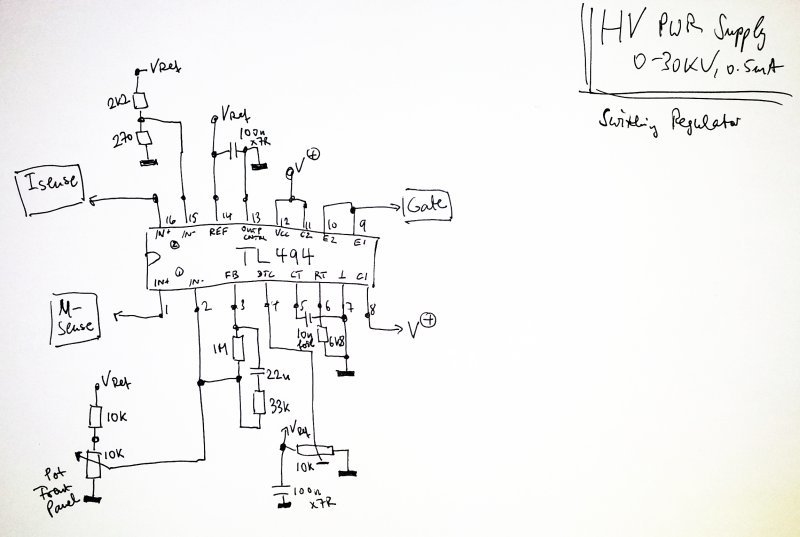
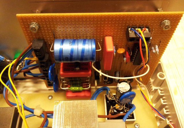
The design, all build around a real classic, a TL494 switchmode regulator.

hvpwr schematic switching regulator

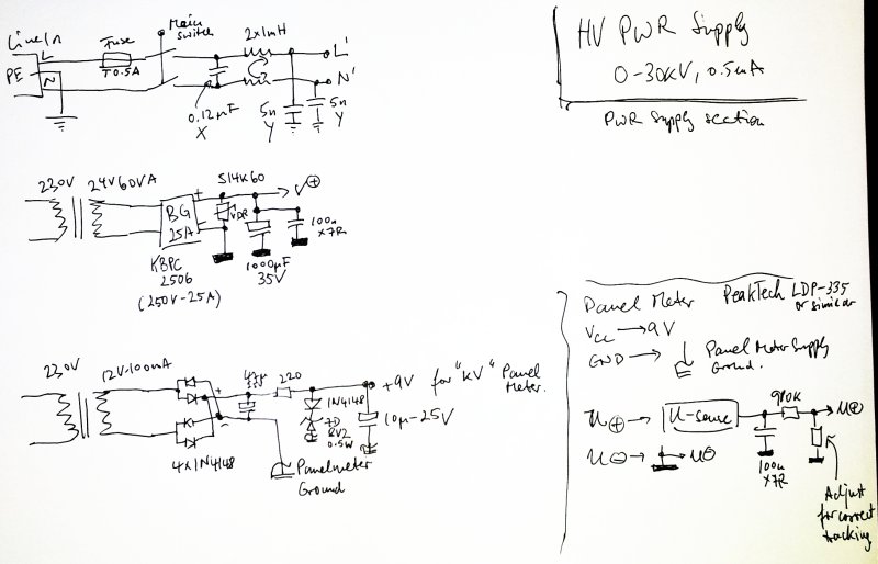
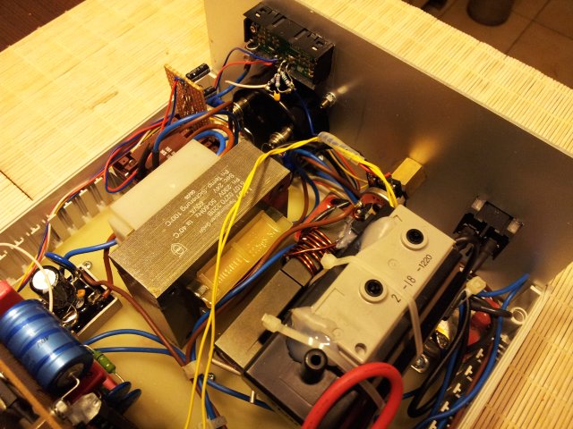
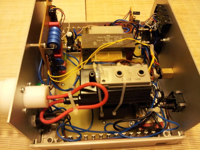
Power is supplied via mains filter, and two transformers. Second transformer is only a needed for the LCD panel meter (Voltage display in kV). Note that the regulator and primary coil is on a floating ground. Earth ground is used for the high voltage coil, with a 1 mA full scale amp meter. Actual output current can be above 1 mA, depite the caption “0.5 mA”. Make sure to adjust the maximum current conservatively, and also the dead time, to keep the output power limited – otherwise, the flyback transformer will suffer and eventually stop working.

hvpwr schematic pwr supply

The most interesting part, the flyback driver and snubber circuits. The snubber circuits were designed with a lot of effort, using a scope to probe the overshoot voltages, etc. – if you change the flyback or primary inductance, make sure the check proper dampening! The BY329-1200 is a fast diode, with rather slow (soft) recovery. This will lead so some extra power losses, but this can be tolerated here. The VDRs add some more protection, but actually, they were added more for peace-of-mind than for any real purpose.
One thing to be improved in further design updates is the gate drive: the gate to source voltage is currently the full voltage of (about 24 Volts), it works, but it is running close to the limit of the IRFP450 device, or even above the limit. Furture circuits will include an independent linear regulator, to run the TL494 from a 15 V supply, derived from the main supply, and maybe a Zener diode added to the gate drive signal path, for added protection agains gate voltage excursions.

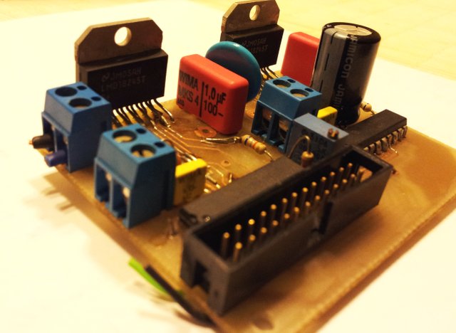
The IFRP450 is driven rather hard, via a 47 Ohm gate resistor, and has very small switching losses. No heatsink required, mounting it to the rear panel will provide ample heat dissipation.

hvpwr schematic flyback driver

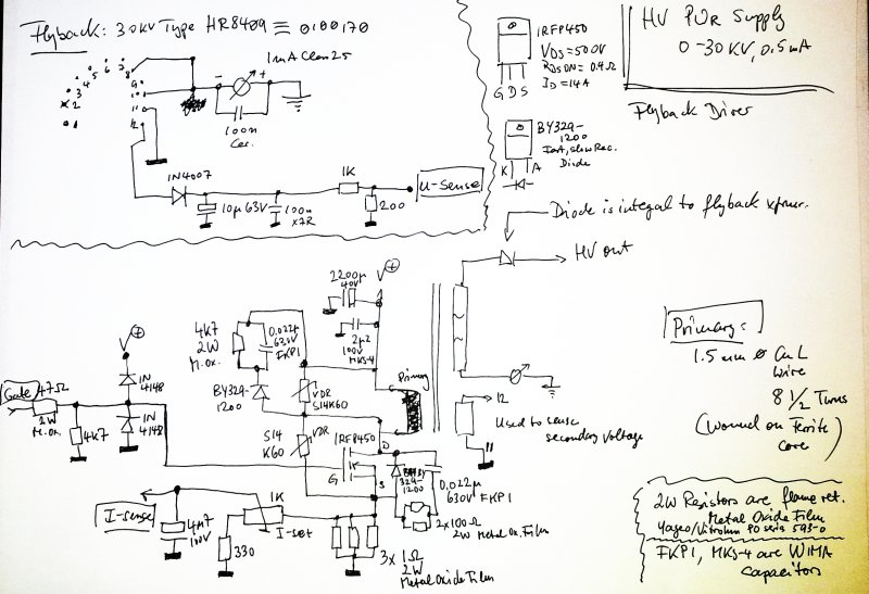
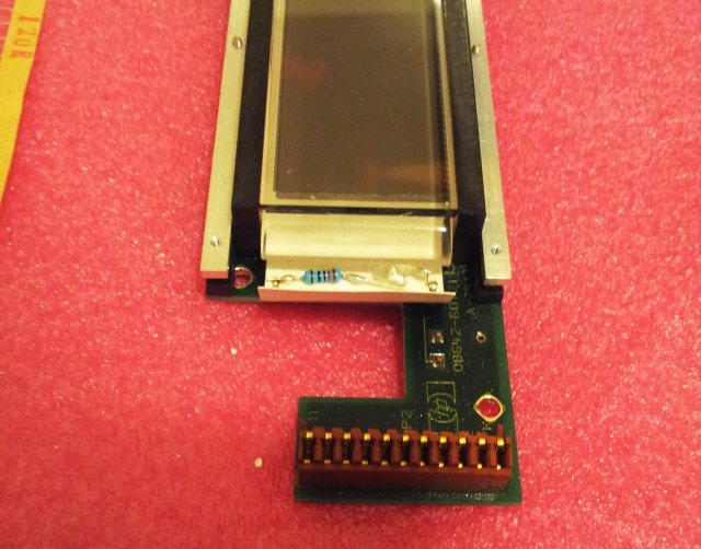
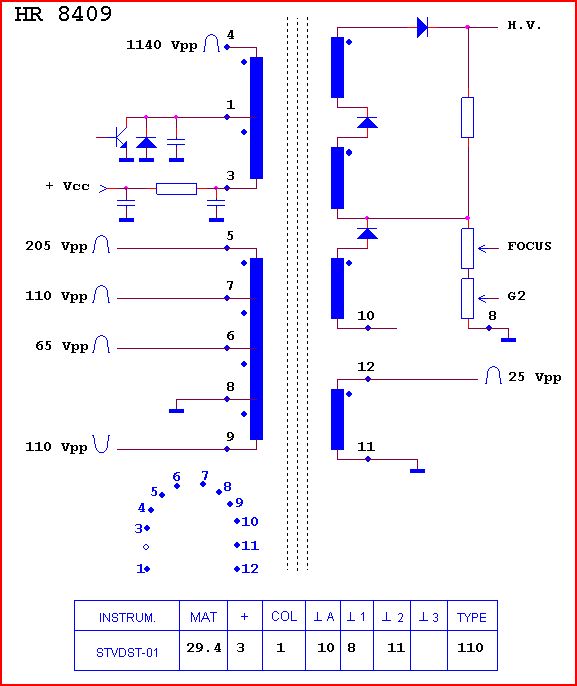
The flyback itself, a 0100170 equivalent to HR 8409 type. The only coils used are the secondaries. The high voltage coils, for the output, and the 11-12 coil, for the voltage feedback. The voltage derived from this coil by half-wave rectification is a very accurate representation of the high voltage output. This has been checked at multiple voltages and load conditions!
The primary winding is 8-1/2 turns of rather heavy copper wire. You can also twist multiple thinner wires, if no thick wire is handy. I used double-isolated type; the device below is just a lab demonstrator for personal use, for professional cirucits, it is suggested to use PTFE (Teflon) or silicon tubing to provide additional isolation of the primary winding from the ferrite core.

Keep your fingers (and other wires) off the other primary windings!! These carry dangerously high voltages, at significant power, and might be more dangerous than the acutal high voltage secondary!
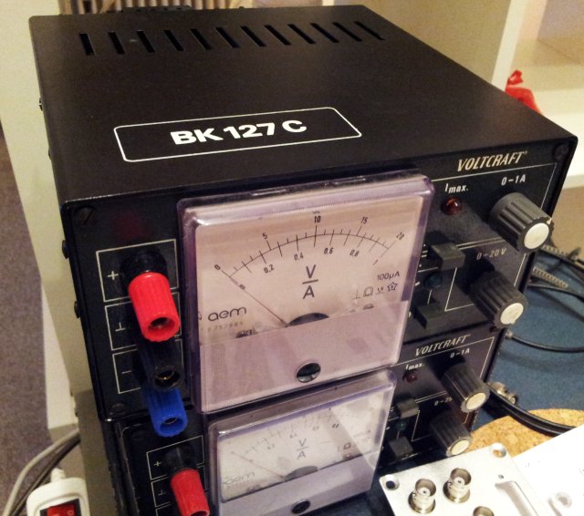
hvpwr flyback hr 8409 equiv 0100170

The actual unit:
hvpwr front panel

hvpwr inner workings 1

hvpwr inner workings 2

hvpwr inner workings 3

hvpwr inner workings 4

hvpwr rear panel

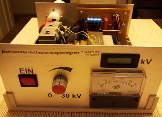
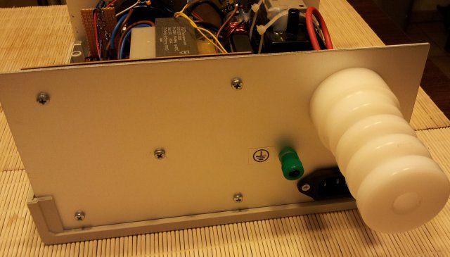
The rear panel has the high voltage output: a big isolator, machined from HDPE plastics, with a 4 mm receptacle hidden inside.

Stepper and Multi-phase Motor Control: LMD18245 based driver

For quite a few projects, I need to control DC, stepper or similar motors, with moderate power, anywhere from 0.5 to 2 Amps. For smaller motors, I have a well-established circuit using ULN drivers (to be described elsewhere), and for powerful motors, I generally use the reasonably inexpensive Leadshine or Leadshine-compatible controls – but for the intermediate range, below circuit has provided great service in many applications over the years.
Mostly, it is used together with bipolar stepper motors, like, in a big engraving machine build about 10 years ago. Recently, I re-used the design to control a rather uncommon 3-phase stepper motor.

The original prototype:

lmd18245 driver

The key part is a LMD18245 from National, now, Texas Instruments, about USD 10 per piece. This is a full H bridge, with 4-bit DAC current control, integrated diodes, and utilizing DMOS technology. It is working up to about 3 Amps, 50 Volts; and has overcurrent/overtemperature protection. Not bad, and it allows for very small designs, without going to the trouble of thermal engineering of power SMD components used in more recent designs (and reliability issues, if such design is not properly done).

The LMD18245 uses a remarkable current sensing technique – the main DMOS switches are made up of about 4000 elements, and only one of these is used, along with a current sense amplifier, to provide a 4000:1 scaled version (250 µA per Amp) of the coil current. This eliminates the need of heavy/expensive low-ohm low-inductance resistors.

lmd18245 dmos current sense

To protect the circuit, two capacitors are used – a 1 µF film capacitor, close to the VCC input of the LMD18245, and a 470 µF electrolytic (1 for each pair of phases).

The digital interface is very simple, and has been used in assemblies of multiple motors/multiple phases with success. The data bus input is buffered by 74LS374 edge-triggered D-flip-flops. Many units can be connected to a common bus, using a ribbon cable, and solder bridges for the address (LS374 clock) lines.

Typically, these are set by a micro-processor, using a look-up table (if MCU pin number is limited, a shift register, 74LS164 or similar, can be used instead). This allows full control of magnitude of current (4-bit DAC), and direction (via H bridge).

lmd18245 driver schematic

Judging from experience, the LMD18245 is a very robust device that can be employed of all kinds of motor control, in particular, if you need a easy to implement, but still fully customizable, reliable solution.