All posts by Simon

Wiltron 6659A Programmable Sweep Generator: 10 MHz to 26.5 GHz, in a single sweep…

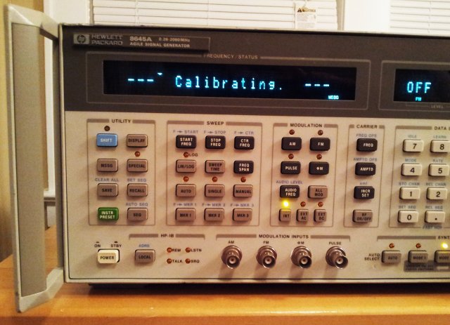
This instrument just needed a few adjustments, still, very interesting to look at.
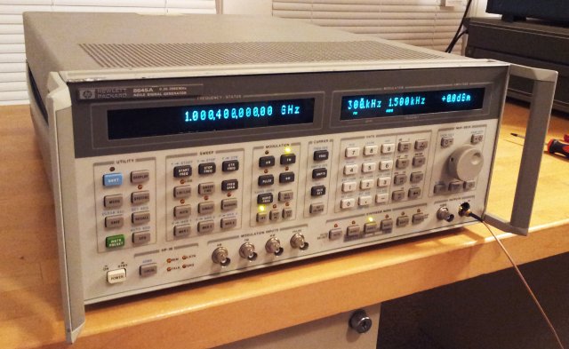
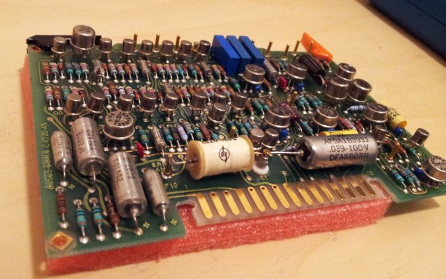
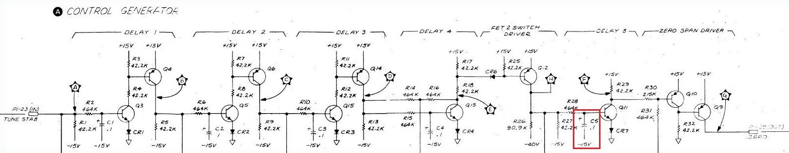
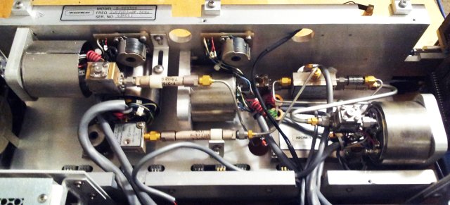
It is of a very classical design – 4 YIG oscillators (2-8, 8-12, 12-18, 18-26.5 GHz), a coupler, a detector, and all the driver and ALC circuitry to make this work.
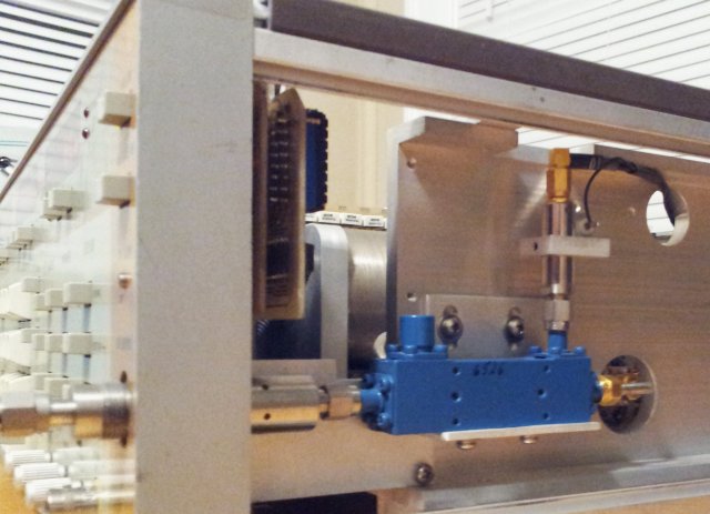
There is also a Wiltron-brand downconverter that provides the 10 MHz to 2 GHz output, by conversion of a 4610-6600 MHz input, with a 4600 MHz LO.

The YIGs are all of best quality, Avantek parts.

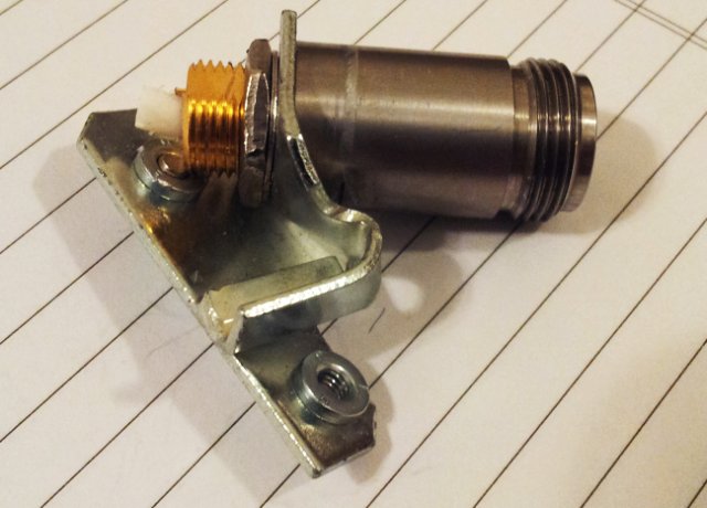
The coupler, for the ALC loop, a Krytar ultra-broadband part, with a biased detector.

wiltron 6659a

6659a alc detector

wiltron 6659a yig assy

wiltron 6659a front

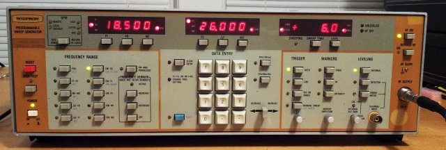
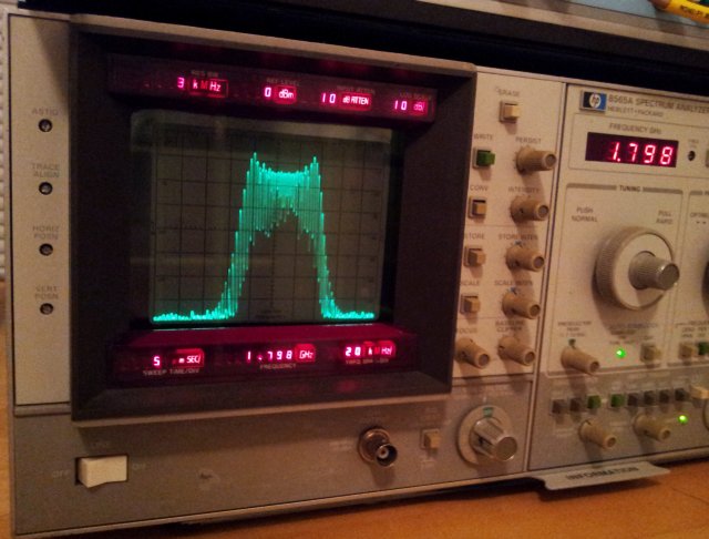
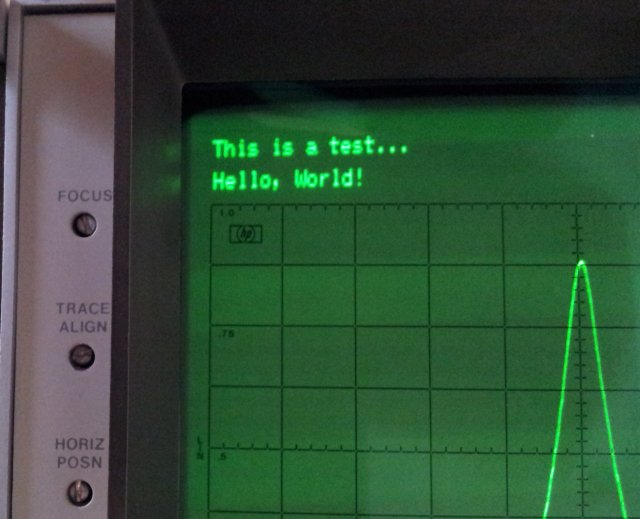
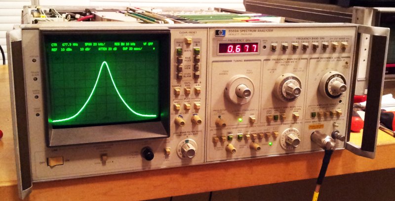
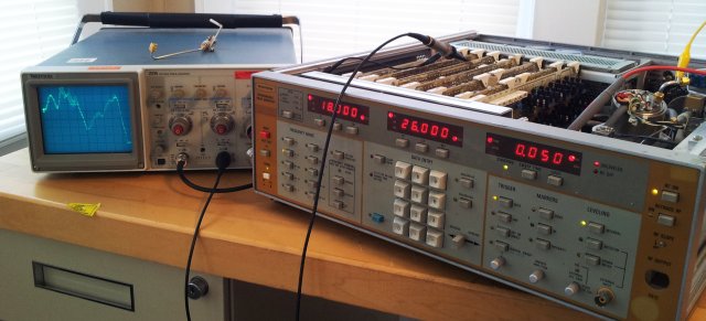
The generator provides ample power, 10 dBm or more, over most of the bands; about +6 dBm, at above 18 GHz – and, around 23 GHz, there is a dip in the power curve (see scope screen, showing the ALC/power signal vs. horizontal sweep). Checked the bias (was set at a constant +11 V) – changing it, and going up to +15 V, no change. Also checked the power directly at the YIG output – still, the dip. So it seems, nothing we can do about it, but for most practical purposes, about 0 dBm will be plenty, at any frequency.

wiltron 6659a power measurement

After some more alingments, the frequencies and bands are spot-on (no need to re-programm the linearizer EPROMs – all YIGs are still tracking perfectly fine), some some cleaning, using 50% isopropyl alcohol – done.

The only thing left to be done – a back-up of the 2716 EPROMs that still hold the firmware, after about 30 years.

Dell PowerEdge SC1425, 2x Seagate 3 TB NAS S3000VN000, Ubuntu 14.04.1 LTS: server upgrade

Over the years, a number of manuals and datasheets have been accumulating, also because of my inclination to keep a copy of more or less every document I have used for repair jobs, etc. – sometimes servers go down, and the files disappear in the vastness of the internet.

For some years, I have been dealing with USB drives and NAS storage devices, to keep local copies, and to keep files accessible, but this has become troublesome with space running out, and multiple copies, on multiple drives. Time for a better solution.

(1) A Dell PowerEdge SC1425: 64-bit dual Xeon 2.8 GHz processors, 2 GB RAM. Available surplus, essentially, for the cost of shipment.

poweredge sc1425

(2) 2 pcs Seagate 3 TB drives S3000VN000, these are NAS-optimized drives – essentially, the same hardware as common desktop drives, but targeted for 24/7 operation, with specifications that correspond to long-lifetime “medium”-performance requirements. Performance – this is a private fileserver, and reading rates of 20-40 MB per second are plenty, you don’t need any 10K/15K drives to achieve this.
The drives are operated in RAID1, full redundant.

seagate st3000vn000

(3) Ubuntu 14.04.1 – server. This is a common solution that can provide both Samba (Windows shared folder) and web (Apache) server functionality, at no cost.
Also, it provides the RAID1 functionality (software raid).

Putting these things together, not a big deal – one should think. It took quite some hours to figure out all the settings to get the RAID1 working, and all the files transfered from the old harddrive (~150 GB, the essentials).

Another item to consider, the noise. The SC1425 will be put in the attic, so there is no issue, but don’t consider having this machine anywhere close to where humans reside – it is noisy. 4 fans, cooling the dual CPU, right in the middle of the case (red frame).

poweredge sc1425 2

Some performance stats:

raid1 performance read

raid1 performance write

Roughly 100 MByte/s read/write on the RAID1 pair – perfectly fine to support a 1 GBit/s network speed. Over Samba, I get about 25 MByte/s.
Maybe you noticed the name of the machine – arctur – wondering what it is? – a star, quite a bit bigger than our sun, and not too far away – just about 11 parsec, or 37 light-years! Glad that data server is just a few nano-seconds away, at least, counting the light path.

8645A Agile Signal Generator: power-up, lots of mechanical repair – finally, calibration, and some first tests

The 8645A has been a real challenge. Not electronically, but with all the mechanical damage.

Most of the defective parts are now fixed or replaced, the last one missing:
8645a damaged connector assembly

The front connector and bracket, badly damaged – this will need to go back with me to Germany, don’t have the right tools here (anyone out there with a metal workshop, in the greated NYC area, let me know!). Will see if I can bend this back, or machine a replacement from aluminum alloy. Also, one of the screws is broken off and stuck in the thread – all pretty laborious to repair.

The temporary set-up – connected a SMA f/f adapter, to get the signal out.
8645a temporary connection

Electronically, major success! Not going into any details for now, explaining the inner workings of the 8645A would take hours. But, it is now back to a stage where power can be supplied to the circuits, and watch out, this is the first result:

8645a self cal

… after several minutes, still no change – checked the manual – and the self calibration can acutally take 5 minutes or more, so I am patiently waiting. Finally, this result:

8645a result code 0

Sounds good.

Went quickly through all of the basic functions, and the machine seems to put out almost +20 dBm over the full band, stays perfectly phase locked, and, as far as I can tell with the 8565A, it is pretty clean.

Machine under test –
8645a working

– showing a ~1.7 GHz signal, FM modulated, 30 kHz depth, 1.5 kHz audio.
8645a fm check

For now, repair-final check on hold, with more tests once the connector is back in place.

The many hours spent so far, certainly worthwhile,for a machine that cost about USD 39.5k in 1990, close to 90k nowadays… all its major capabilities, well described in the HP 1990 catalog.
8645a hp catalog 1990

Micro-Tel MSR-904A Microwave Receiver: a wire, another 2N2905A – repair completed (!) – sensitivity test passed

After quite some heavy work with the MSR-904A, we are close to completion. The last defect, supposedly last, was an issue with the 0-9 V internal tuning voltage – could not get it to change from 0-9 V even with all adjustments suggested by the manual, and looking at the schematic – no other way to adjust. There can be drifts of some resistors over time, but all checked and very much as spot-on is they can be.

So, the issue comes from a part of the AFC circuit – there is some gain switching with a 4051 CMOS switch, and as it turns out, this was missing the -6 V supply voltage – causing a positive voltage at the output, which upset the tuning assembly, even with AFC disabled. The wire, not sure if it was broken when I received it – well, easy fix, but took me the best part of 2 hours to find it.

With the machine now ready to be put back in service and fully operational, a few hours warm-up, and all the oscillators and YIG filters fine-tuned, I slipped with the screw driver – a spark – and the 250 MHz amplifier was dead. Fortunately, no major defect, just the 2N2905A that switches on the power for the 250 MHz amp. Added a “new” one, 1984 vintage…

Finally, closed the lid, to keep my screwdrivers out, and did a quick check of sensitivity at about 1.7 GHz (because I have a really well calibrated 0.1-2.1 GHz source, a HP 8642B here already on the bench and did not want to carry around heavy microwave synthesizers…).

Here, the result, which I would call pretty much satisfactory. Doesn’t get much better unless you cool down the receiver with some liquid helium.

msr-904a sensitivity test

The machine, in all its beauty.

msr-904a completed

msr-904a completed 2

HPAK 8645A Agile Signal Generator: pushing it back in shape, Chinese spares

The 8645A – see earlier post, reached my workshop in a really bad shape, electronically dead, and severely damaged. For any reasonable effort, damaged beyond repair.

However, I do this for a hobby and there is no rush, and I just can’t take this thing apart for scrap metal – the case suffered damage, but the inner parts, no major mechanical issue.

For most of their 1980-1995 equipment, HP used a so-called “System 2” modular case, mainly, die-cast aluminum alloy. The 8645A is not much different – the bottom and top lid are different (to provide better shielding than the regular System 2), but the front frame, it is the same.

Looking around at xbay – found a complete front system 2 front assembly, System 2, from a 8782B Vector Signal Generator. The Chinese vendor, he seems to make a cut by taking apart equipment, and selling it for parts – it wasn’t quite cheap, but still, for a 8645A, to get it back into service, it seems pretty much worthwhile.

It arrived already after about one week.
8645a new frame
8645a new frame 2

Not in best shape, but usable.

This assembly also has quite a few BNC connectors, and a precision N connector, all very handy to fix the replace the snapped-off parts.
As it turns out, the N connector is of a different length, but never mind, I have some more spares around.

The front panel assembly, it is apparently one of the weak points of the 864x series.
Two layers of rather soft aluminum, a ~0.8 m plastic sheet that also acts as filters for the fluorescent displays, and a thin outer layer with the labels.

This is quite easily pushed in, if force is put on the BNC connectors – it is always best to safely secure the instrument at the corners during transport, and to attach handles.

8645a front panel 1

The layers are held together by glue, and it seems, HP has used a very sticky, but not permanent type – with great care, it can be separated. Key thing is to keep the sticky surfaces clean, and they are best protected by a polyethylene foil.

To flatten things out, a carefully adjust iron is a handy tool – with the plastic sheets put in between two layers of non-stick paper.

8645a plastic sheet ironing a

8645a plastic sheet ironing

The more laborious part – the flattening of the aluminum panels, with a hammer, and a piece of wood, and about 2 hours of work.

The result – all things glued back together, pretty happy with the result.

8645a front panel repaired

8645a front panel repaired 2

Sure, there are some little blemishes, well, fair enough!

Now we just need to get the inner workings going…..

Micro-Tel MSR-904A Microwave Receiver: three bad guys, an a revised YIG filter

There are a few remaining items that need to be fixed:

(1) The frequency marker doesn’t work
(2) The AGC circuit is acting up a bit
(3) The 21.4 MHz IF chain – it is working but gain seems low
(4) The YIG driver – it has too much inherent noise when using the external input (EXT frequency mode). Added a 100 n capacitor (see earlier post) – but this interfers very much with the faster sweep rates, where full YIG driver bandwidth is needed. So I need to add a switch that takes out the 100 n cap, except when in EXT mode (not planning on any super fast sweeps in EXT mode, but definitely need low phase noise)
(5) The ‘signal strength indicator’ is working (a nice LED bargraph), but the offset can’t be adjusted properly, and it moves eratically, at times.

With the manual, the search defect (1) – marker that was so far difficult to track down has an end: the issue is one more of the CMOS switches, a 4052. Well, already the second of these switches which is bad. Maybe, I should just replace all the 4051, 4052 and 4053 switches of the units, as a matter of preventative maintenance. Well, we don’t want to fix things that ain’t broke.

Item (3) – nothing worse that disassembling the IF chain – by all admiration for this unit, the 2nd IF chain is not build for troubleshooting. But, following the instructions, first a check of the control assembly. And, quite to my surprise – a defective transistor switch, using a 2N2905 PNP transistor that provides +15 V power to one of the 24.1 MHz amplifiers – this is switched on and off depending on the BAND setting. The transistor – only had a 2N2904 around, same kind, but a bit lower gain. Well, it works – need to check stock back home in Germany when I get a chance.

These are the bad guys-
msr-904a more bad guys

Item (2) – this was “just” a matter of adjustment. Adjustment isn’t all that straightforward – and the manual doesn’t cover everything. Needed to peak the 250 MHz amp/AM detector circuit – there is a tuned amplifier inside, which has and adjustment capacitor not described in the adjustment instructions – fortunately, pretty clear from the schematic.

Item (5) – turned out to be a 1458 opamp not working properly, replaced. Pretty easy – most of the integrated circuits are in sockets. Sorry, no picture of the defective 1458 😉

Item (4) – added a good Chinese brand SIP reed relay, PAN CHANG SIP-1A05:
sip-1a05

Routed a wire with the EXT signal (low when activated) to the YIG driver board. This is now taking the 100 n cap out of the circuit, unless the EXT mode is active. Added a protection diode, to avoid voltage spikes damaging the TTL circuit driving the reed relay.

msr-904a a7b3 yig driver

msr-904a yig driver bw limit ext mode

The 100 n cap and reed relay is installed parallel to the R4 resistor – same as for the C5 capacitor, which is activated in CW mode.

Micro-Tel MSR-904A Microwave Receiver: manual found!

I had almost given up. It seemed that a full manual of a MSR-904A would be perfectly unobtainium. Well, most secrets of the MSR-904A were reverse engineered anyway, but there are some subtle details and adjustments – just a bit arbitrary to do without proper documentation and at a least a bit of insight into the thoughts of the designers of this marvelous apparatus.
One reason might be that these units were long banned from export and mostly governmentally owned. Eventually, the units reached the secondary market, but the manuals, they rest in some archives, or have long been disposed off by the agencies.

Now, to my greatest surprise – a copy of the manual has been located – in Germany. The paper copy, it seems to belong (or have belonged) to a certain H. S. in Webenheim, a place, a mere 72 miles form my German home.
Another fellow German must have scanned this, and again, another fellow, send it to me, electronically. Albeit, not for free, but, fair enough.

msr-904a manual

It is complete with all adjustments instructions, explanation of how it works, parts list, and SCHEMATICs.

Here, a block diagram of the IF chain – without the 160 MHz 2nd IF output option (by conversion of the 250 MHz 1st IF using a 410 MHz LO) installed in the unit I have for repair.

msr-904a if chain

Screening through the manual, the complexity of the thing is pretty much amazing. All without any controllers or processors – but there is at least one programmable part, a PROM that has the filter switching matrix. Come on, this could have been done with a diode matrix!

AIOM: updated schematics, differential input bias, high-impedance input protection and amplifier

Some progress, with the universal analog input output module, analog response analyzer, or line tracer, digitizer – however you want to call it. Added a few features – a bias supply for the differential input, and a high impedance amplifier (and a bit of protection circuitry) for the single-ended input.

First the bias supply – to allow a wide range of input voltages, say +-20 V (even below ground and well above the positive rail), we need a resistive divider network, and this needs to convert a differential voltage (with absolute voltages centered around ground), to a differential 0 to 2.5 V input, centered around 2.5 V (the internal bias of the ADC). A little calculator is used to find the right resistors and bias voltage. About 2.65 V will do the trick, for the desired input range, and resistor combination. Bias current is just about 1 mA or so, easily sourced/sinked by a OPA703 opamp.

adc input bias calculator

This input is mainly designed to sense low impedance sources, e.g., current shunts or supply voltages (lead compensation, or similar configurations). So the ~50 k input impedance will be perfectly fine.

aiom schematic 1 of 2

aiom schematic 2 of 2

The general circuit, nothing really exciting about it – the AD7712 has a 8 MHz crystal, will run easily up to 1 kHz conversion rate. But mostly, it will be run at 50 or 60 Hz, to suppress any mains related noise, or even at 10 Hz.

A quick test showed that the USB communication is working (using a JY-MCU ATmega32L minimum board) – just waiting for some long waiting times and train travels to write a simple user interface, to control the outputs and the data acquisition by Windows GUI. For plotting and data analysis, I will resort to gnuplot and/or R, not re-inventing the wheel here. Maybe a simple preview screen.

HPAK 8569A Microwave Spectrum Analyzer: some adjustments, an ultrastable 10 Volt reference, GPIB test- repair completed!

The manual for the 8569A describes a series of performance tests – not all of them were completed, but most. Fortunately, the IF chain doesn’t need adjustment. Still, it took nearly three hours to get the YTF tracking, the A/D converter/digital display section and other display related circuits adjusted. The log amplifier was carefully tested as well, all perfectly in tune.

The most amazing find – the internal 10.0 V reference was found at 10.00004 V. That’s +4 ppm – most likely, better than the voltmeter I am using to measure this.

The reference circuit, according to the datasheet, is uses a regular HP/RCA low noise opamp of the late 1970s (selected 741), and a +-10 ppm/K 1N827 temperature compensated zener. As it turns out – the actual part used is a 1826-1058, an OP-02 equivalent (0.65 µVpp noise, 8 µV/K drift), much better.
Resistors in blue frame are +-10 ppm/K tempco. Others are regular, +-100 ppm/K resistors.
The circuit layout – very much refined, a marvel of analog engineering – guard traces all around!

8569a 10 v reference circuit

It is run at exactly 7.44 mA, using the 10 V reference to set the diode current – to minimize the temperature coefficient. See this diagram from the 1N827 datasheet:
1n827 tempco vs zener current
Seems that after 34 years of aging, it is perfectly stable now.

Back-up of the internal EPROMs (4x 4 kbyte!) stored – just in case they fade out over time.

Last step – test of the GPIB functions – and, no issues at all.

Writing to the machine:

8569a hello world

And receiving plot data back (two signals, close to 100 MHz, -10 dB):
8569a plot

At its final place, for now, on top of a 3585A – total of almost 200 pounds of test equipment. Hope the bench won’t cave in.
8569a working

HPAK 8569A Microwave Spectrum Analyzer: tuning stabilizer/tickler repair

After fixing the display and front panel related issues (attenuator, “0 dB” indicator), the only major defect remaining so far is the tuning stabilizer circuit. Once the span is set to below 100 kHz, it is activated – and sets the unit to zero span, rather than the span selected, permanently. Only when the stabilizer is disabled (there is a button on the front panel), the span is back to normal.

The source of this issue – most likely, the A14 tuning stabilizer assembly. Switched the board (part number 08565-60018) with the identical board of a 8565A – and, as expected, the zero span issue is gone!!

Now, we just need to fix the board.

The description in the service manual is actually pretty clear – the circuit uses a 1 MHz harmonic sampler, to keep the frequency of the LO stable. The initial lock is achieved by setting the analyzer to zero span, finding a frequency close to 1 MHz that represents a lock point. This frequency is controlled by a voltage, and a very long lasting sample-and-hold is used, than employs a special construction of a HP reed relay, and a PE/PTFE(?) lowest leakage capacitor – the white coil in the front, left, and the the capacitor, front, right – in the middle, a PTFE isolated post, going to a FET gate.

8569a a14 assy 08565-60018

Certainly, a very special capacitor. Once this is achieved, error voltage of the sampler is used to steer the LO, and the analyzer is returned from zero to normal span mode.

The sequence of all these steps – controlled by a very interesting chain of transistors, resistors, and capacitors – nowadays, just a few lines of program code… but, nothing better than a handful of discrete high quality components.

The “control generator”, see schematic below – it is not controlling the sequence properly – and, again, a defective cap. 0.1 µF (!), tantalum – red frame; a few 100 Ohms – near short. No way that this can get charged, and let the sequence proceed.
08565-60018 control generator schematic

Replaced it, with a regular 0.1 µF cap (why did they use a tantalum??), and: A14 assy working again. 20 kHz span, 10 kHz resolution bandwidth. Working just fine – at all frequencies up to 20 GHz, the highest I can check here.

8569a working stabilizer 20 khz span 10 khz res bw

The black sheep (date code: 1980, week 7):

8565a a14 culprit

We can’t argue that they didn’t skim on parts – at the time, certainly, one of the best 0.1 µF tantalums available.
Parts list specifies 150D series, MIL–PRF–39003 mil-spec qualified high reliability hermetically sealed cap:

150d tantalum