All posts by Simon

Micro-Tel MSR-904A: some basic repairs

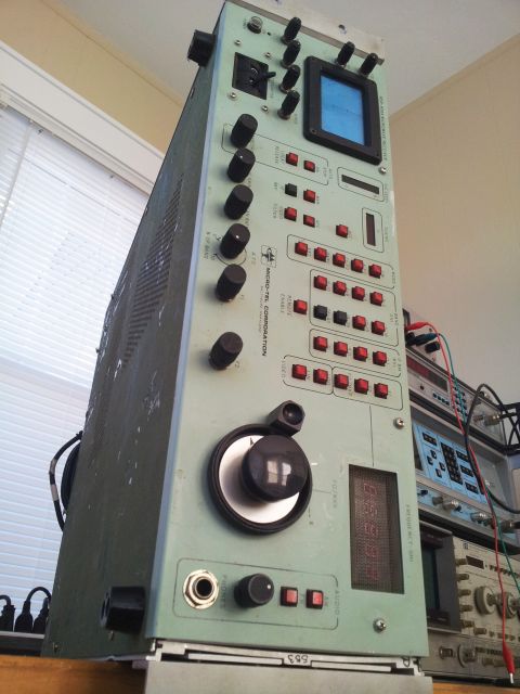
Quick initial assessment, these are some of the items that will need attention:

(1) Exterior. Need to fabricate instrument feet, re-paint the panels, handles are missing – either need to get spares, or fabricate replacement handles (can only be done back at the main workshop in Germany, lacking machine tools here).

(2) The ground leakage -need to check the power supply. Hope it is not the transformer or other critical part.

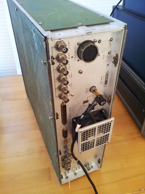
(3) Power cable. Absolutely non-standard! Uses a BENDIX connector, 3 pin, type PT02E8-3P-027.
msr-904a mains connector bendix PT02E8-3P
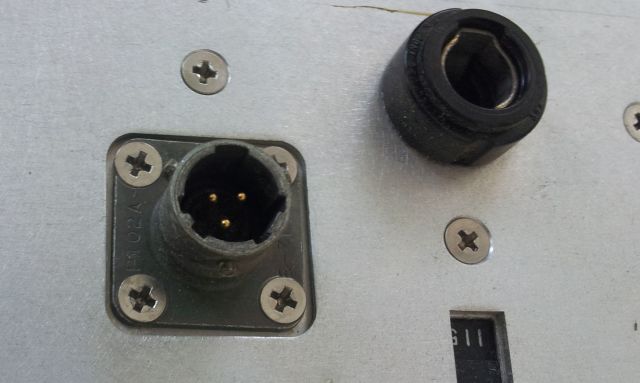
Interestingly enough, found a suitable cable, especially made for the MSR-904, on xbay, Army surplus! PN: SC-D-627094-5FT NSN:5995-00-165-3806, the guy has more then 10 pieces – seems the Army was really worried to run out of cables for their MSR-904s.

(4) The frequency display works but doesn’t show the right frequencies.

(5) The F2 adjustment (upper sweep stop frequency in F1-F2 mode) doesn’t work.

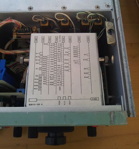
(6) Figuring out the major adjustment pots – this is all documentation I have:
msr-904a documentation

(7) Figuring out the pinout of the “Monitor” port (intended to connect a storage scope, I might connect a digitizer), and of the “Remote” port – the remote control signals (TTL).

(8) Figuring out the external frequency control and phase lock voltage requirements.

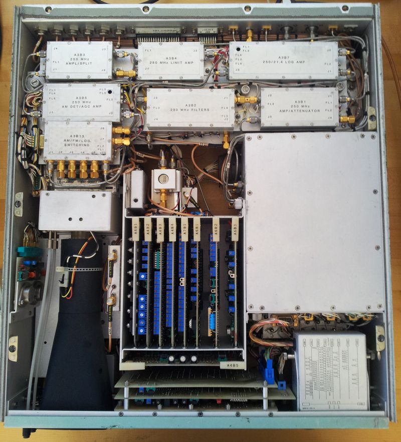
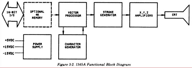
(9) Drafting a block diagram of the RF deck and IF chain, just to better understand the inner workings, and to see, which parts-components Micro-Tel used.

Now, on item (2).

The power supply –
msr-904a triple shielded power supply
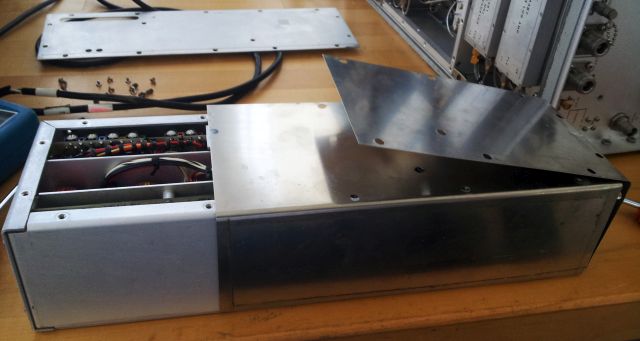
It’s held in place, and held together, by a cup full of screws. And, it has a layer of what is presumably Mu metal (high magnetically shielding sheet metal), to keep the 50-60 Hz in the transformer.

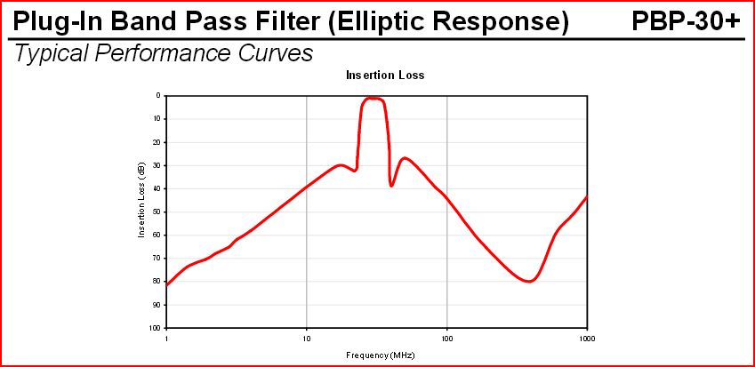
The filter, at the input, it is a sight in itself. Not sure how much it would cost to fabricate a custom aluminum case of this size, and to manually assembly it these days. Parts value alone, over 250 USD.
msr-904a mains filter
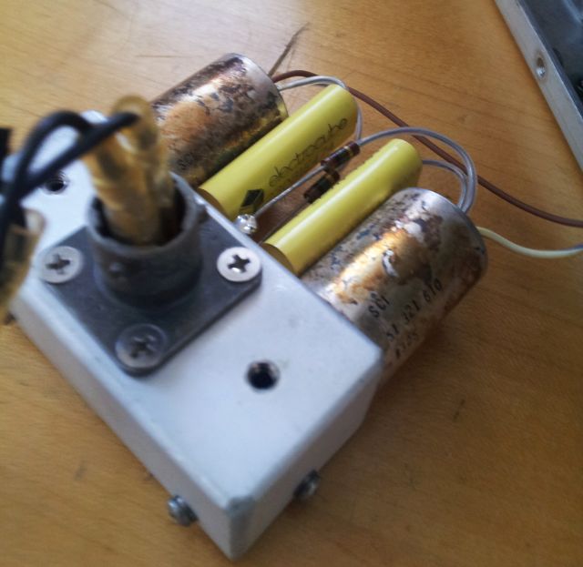
Well, and as it turns out, exactly these parts are leaky. SPI filters, 51-321-610, still available, after being around for 30+ years, at Mouser and elsewhere – 119.64 USD each, 18 pcs minimum order….
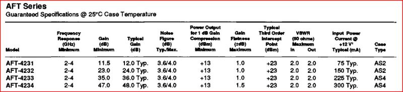
The spec data:
SCI 51-321-610 hermetic RFI filter

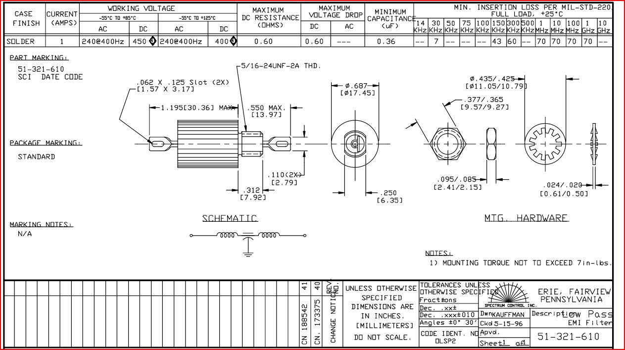
After a quick thought – I will give these parts a miss. With all the shielding, transformers and wires, we can do without hermetic feed-through filters – keeping in mind that also the bottom and top lid of the unit have ventillation holes.

So, filters removed, and wires re-connected… and, quite to my satisfaction, no ground leakage any more – not even a few microamps.

Before putting it back together – quick check of the power supply – all seems to be working fine now, and well adjusted.

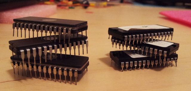
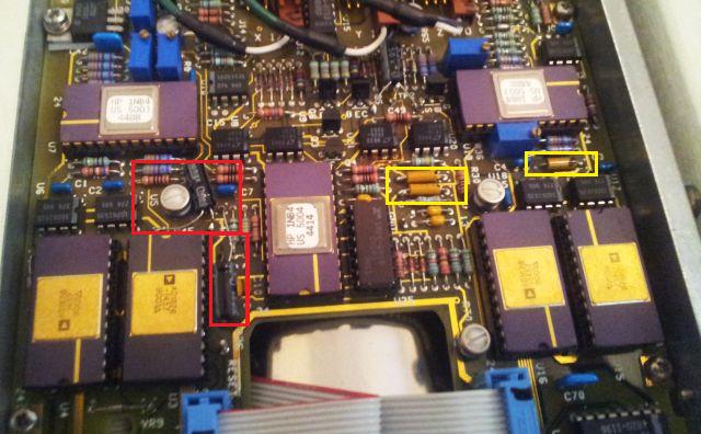
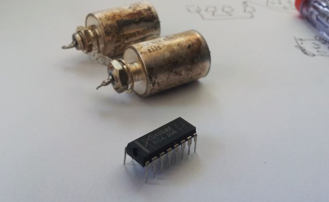
Item (4) – complicated. Took me quite some hours. The frequency meter is acutally a voltage meter, and this is controlled by the tuning voltage, and a complex digital circuit spread over some hard to reach board. After searching around – it’s just a defective CMOS multiplexer switch, setting the gain of one of the voltage conditioning stages (which are needed to handle the various bands). It’s and CD4051, standard item, no problem. Put in a good one, from another part of the circuit that is not criticial at this point, and ordered a few spares, just USD 1.75 for 3 pcs, including shipment, from Macau.

msr-904a a few more broken parts

On item (5) – the sweep circuit is pretty similar to the Micro-Tel SG-811, and for the SG-811, I have the schematics around.
It uses a dual 10 turn potentiometer. 10k.
msr-904a helipot 8106 defective

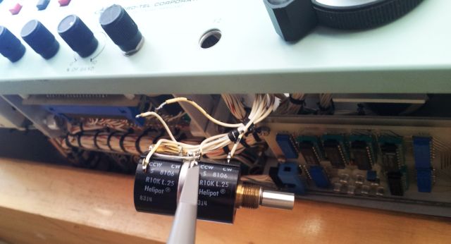
Helipot 6108 series, a type common to high-grade analog-control instruments. Seems that one of the stages (the stage that controls the sweep range) is defective – the hybrid resistance material used for the pot (these don’t use wire, because they are made for high resolution applications) is open at the “cold” end – sweeper is always at full scale.

As these are all fully sealed units, no way to repair – found an exact replacement second-hand, for a reasonable charge. For the time being- changed the wires: the F2 display (controlled by the second stage of the pot, which is still working), has been disabled, and the wires changed so that the acutal sweep range is now controllable – so I can do all adjustments, just don’t get a display for the F2 frequency.

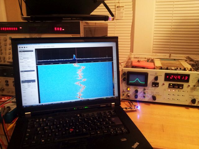
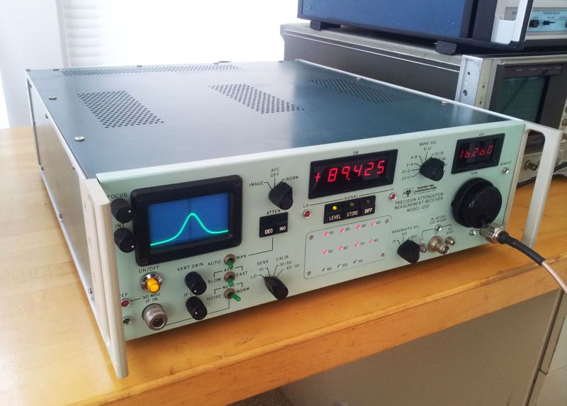
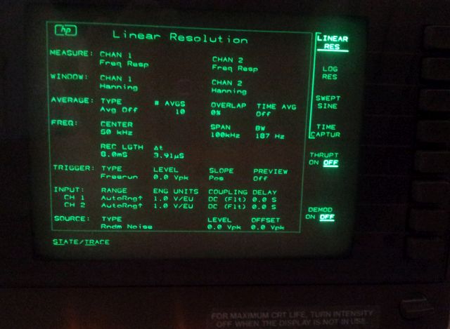
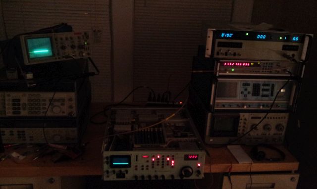
Well, and after all this, the unit is at least basically working, responding to controls, and not triggering any fuses. To move things further, setting it up with a few GHz range synthesizers, and an EIP 545A counter, for some first tests with RF.

msr-904a adjustments

To be continued…

Micro-Tel MSR-904A Microwave Receiver: the big box arrived!

Look what I found on the doorstep yesterday:
msr-904a big box

Wrapped in 20+ feet of bubble wrap, nothing less than a Micro-Tel MSR-904A Microwave Receiver, needing some TLC, later, to be added to a special equipment collection elsewhere.

The MSR-904A. Arguably, it is the last member of a series of 18 GHz+ receivers, build by Micro-Tel at Baltimore, MA, and intended for surveillance work, by governmental agencies. If you ask the right people, these receivers are pretty famous, and have been considered a strategic item for a long time.

They are build using all discrete parts, and hardwired CMOS and TTL logic. After all, many parts, but if you have seen other Micro-Tel instruments, not too unfamiliar. Some say, 80s technology, but actually, is is build in time-less style – from the best components available (not only at the time – these components, YIGs and filters haven’t really improved since).

Some performance data:
Frequency range: 0.5-18 GHz – fundamental mixing; fully YIG pre-selected over the full range (using 18 dB drop-off filter, i.e., three YIG spheres; one preselector for 0.5-2 GHz, the other, 2 to 18 GHz).
1st Image rejection, 70 dB, and 65 dB at above 12 GHz.
IF rejection: >70 dB
IF filters: 100 kHz, 1 MHz, 5 MHz, 30 MHz – quite handy.
IM3: about 5 dBm
LOG and LIN detectors
AM and FM demodulator
Spurious: 90 dBm at input equivalent over full range.
Noise figure is about 20 dB

Note: All in all, 3+3+1+1 = 9 YIG spheres are used, and an uncounted number of filter crystalls. The 100 kHz 21.4 IF filter, it’s quite impressive.

In the 2 to 18 GHz range, a 250 MHz-21.4 MHz IF chain is used, with LO 250 MHz above the signal.
For 0.5 to 2 GHz the signal is mixed with an additional 2.08 GHz from an auxilliary LO. I.e., LO frequency is 2330 MHz (2080+250 MHz) above signal.

The other great things about it:

(1) Fully fundamental mixing, using YIGs – lowest phase noise possible. Fully preselected.

(2) Unit has a 250 MHz IF output, with about 40 MHz bandwidth – this makes this unit ideally suitable as down-converter, if you want or need to receive at medium to high GHz frequencies. Can be directly fed to any SDR for demodulation. The MSR-904A has very small group delay, seems pretty suitable for handling of digital modulation schemes.

(3) It is fully remotely controllable, and has a phase lock input – will hook it up to a ADF41020, and/or a fractional-N PLL, same PLLs as already developed and tested for the Micro-Tel 1295 receiver. Such PLL unit will go along with the MSR-904A, once the repair and proper adjustment and testing is finished. Micro-Tel used to offer a frequency stabilizer (PLL) for the MSR-904A, but I have never seen one offered. If you have one, please let me know!

Two downsides – NO serice manual, no manual or documentation at all. If you have one, even if only for another MSR unit (MSR-901, MSR-902, MSR 903), please, let me know.

Second downside – the condition. Well, there don’t seem to be many of the MSR-904A around for sale any more. One unit I know off, but it doesn’t have the panoramic (scope) display. Other might be available, at outrageous cost. This unit was sold even blow the market value of a fraction of the components.

msr-904a as received - front

Note the tuning know – different from the typical Micro-Tel style. But nevertheless, seems to be the original, unmodified part.

msr-904a as received - top

msr-904a as received - bottom

msr-904a as received - back

The full repair, it will be a major job, because currently, it is a bit beat up – I wish, the earlier owners would have treated it a bit more carefully, and Micro-Tel should have never touched the green paint that just isn’t lasting and a sticky mess on a good number of their instruments – fortunately, only the panels are affected, and these are easy to remove – re-painting already in process!
Also, it doesn’t seem to work well, powers up, but seems to have a leaky supply – keeps tiggering the RCD. It needs a through inspection.

Cosmetically at least, the inner working are in much better shape than the exterior would suggest.

Center – edge-connector boards, mainly YIG driver and analog control. The metal box on the right – the RF box with the microwave stuff. The other items – IF converters, detectors and so on. Everything: very well shielded.
msr-904a top view

2.08 auxilliary LO. Mixers.
msr-904a aux LO filters mixer

A Narda 2-18 GHz broadband -10 dB coupler. Still available from Narda today!
msr-904a narda 4203-10 LO sample coupler

The preselectors: S082-1630 (2-18 GHz, might work up to 20-22 GHz), and a custom Systron Donner 0.48-2.05 GHz YTF.
msr-904a preselectors

3562A Dynamic Signal Analyzer: LCD retrofit NewScope-5

Yet, another job related to the 3562A, same machine that also had the ROM board defect. This unit also has a weak display, and I have been asked to check replacement-repair options.

After a brief search, there aren’t any spare CRTs around, for the 1345A display used in the 3562A. The last good ones might have been purchased-stockpiled some years ago, by corporation that need to keep equipment going.

Well, fair enough. Luckily, failed CRTs and their limitations are a common feature of dated test equipment. So other have already invested time and effort to provide a solution: the LCD retrofit.

Why not just replace the whole instrument, with something new, up-tp-date, and more manageable? Several reasons:

(1) Many clients have proprietary-custom software running certain automated tests, using certain types and specs of test equipment. The final product specs have often been agreed upon with the OEM, in contracts that are a big hazzle to change. Some of these products, in fact, most, have long service life, so the test rig needs to be kept alive, more or less, at any cost.

(2) Cost – well, new test gear of the proper kind is outrageously expensive. Not taking about plain stuff here, but powerful equipment, network analyzers, spectrum analyzers.

(3) Servicabilty: talking about smaller businesses, not big corporation, often it is quite handy to stick with somewhat dated analyzers etc, because they are perfectly up for the task, the operators are trained, both in using and serviceing them, and often, spare units-parts units are around and can be procured at a fraction of the cost of repair of new equipment.

(4) Quality. Arguably, and except for new digital signal-fast scope stuff, the instruments build in the late 80s and early 90s might be the best ever build. Most of them have specs and typical performance far above what most regular quality can provide nowadays. The reason is simple, in the 80s, these rigs were build for the military and related agencies as the key target market. Nowadays, for consumer electronics, consumer communications… One exemple: the HP 8566B spectrum analyzer. Not sure about the price of such equipment nowadays, if build new – certainly 6 digits. On xbay, they go for about few cents per USD list 1985 list price… and be assured, no big deal to get them working in-spec.

The LCD replacement kits have come down in price considerably – earlier on, still USD 1000+, now, check this out:
NewScope-5 offer
USD 400. Not bad. This includes display. LVDS driver. And certainly, the controller board, to adapt the display to the 3562A.

Here, from the inside:
3652a lcd conversion newscope-5

The display: it’s a rather dated SHARP LCD DISPLAY, LQ057V3DG02, TFT 5.7″, 640×480. But rather then stockpiling CRTs, I now have a few of these in stock now – found them for about 15 EUR each surplus – this will allow service of the LCD-retrofit units, for years to come, without any need for modification to fit another type of LCD display…

I can tell you, such retrofit is worth every dollar. If you have any of the CRT analyzer with the screen gettin dimmer. Don’t hurt your eyes.

3562a lcd conversions newscope-5
A quick glance at it – it’s great to work with it – color display, rather than dim green display.
The color settings work fine for the most part – there are some little bugs in the NewScope-5, related to the text color, in some menues (first character has different color). However, this has really no impact on the great advantage of such LCD retrofit.

3562A Dynamic Signal Analyzer: EROMS fixed, finally!

The last and only remaining item to get the 3562A with the defective A3 ROM Board (03562-66503) back into service, replacing the defective EPROM. Well, I thought this would be a 30 minute job, but it ended up taking a few hours longer. Why? Multiple reasons:

(1) A bug in the AVR eprom reader software, specifically written to read the 3562A rom board (and similar boards, or other instruments – software always needs some adaption). One of the address lines was not toggled-ended up with corrupted data read from the “good” rom board.
Learning for today: always check the EPROM data read for validity, by checking for repeat patters, and by reviewing all the byte values. There should be at least a few 0xff values, otherwise, one of the data bus lines may be broken.

(2) Turns out, there are two versions even of the Rev B rom board, same part number, but eproms U118 and U218 that have the checksums are different. So, needed to desolder these two as well, and replace with the updated version from the working board.

The good ones on the left, the bad guys on the right…
3562a re-programmable vs one-time-programmable eproms 27256

(3) With all this, my eprom programmer, the only one I have that can handle 27256 EPROM had a defective jumper! No contact on one of the address lines….

After all these efforts: that’s the board, after repair:
3562a rom board

The replaced EPROMs are now in sockets – just in case, should they ever fail again.

Just in case you have to do a similar job – here are the EPROM images. Keep in mind, Rev B, 36x 27256 EPROM (sure, you can also use 27C256).
hp 3562a A3 ROM BOARD rev B

And, finally, let’s switch the power on-
3562a rom repair - complete!

All tests passed!

Note – just discovered, someone is offering a spare 3562A ROM board for about USD 100 on xbay…. well, well, but in the end, better a thorough repair, with all EPROM images captured, than just switching some board!

Avantek AFT-4231-10F 2-4 GHz Amplifier: some characterization and modeling

The task for today – characterization of a bunch of microwave amplifiers, Avantek/HP AFT-4231-10F. These are quite rugged and affordable components, widely available surplus, and hermetically sealed – will last forever, if things are not messed up completely.

aft-4231-10f under test

The specification however, it’s not quite clear, and no detailled information could be found on the web. That’s why I have been asked to come up with measurements and a calculation model that allows to estimate the gain (and the actual maximum output power, and the necessary input power, to reach close to maximum output), at any given frequency and input power. Also, it needs to be checked how far above 4 GHz this device still works.
Last item is to measure the supply voltage sensitivity of the gain, to get a feeling on the required stabilization, to avoid incidental AM on the signal.

The datasheet –
aft series amplifier

The only equipment at hand at my temporary workshop here, a microwave source, EIP 928, and an HP 8565A spectrum analyzer was used to measure the gain at various input levels. Accuracy of this setup is about 1 dB.

Some of the results (0 dBm input: blue diamonds; 10 dBm input: green triangles):
aft-4231-10f pout at 0dbm and 10 dbm pin vs frq

To get a proper continuous description, these data were fit to a non-linear function, fractional polynomial term (fits are done using Tablecurve 2D, an excellent program, highly recommended, but doesn’t come cheap):
gain fit
The gain fit (0 dB input) can also be used to describe the maximum power, with some scaling factors – this considerably reduces the number of parameters needed, and the calculation effort later, when implemented in a microcontroller. Black lines in above diagram show the fit results.

For the gain compression, a 2nd order polynomial is used, and scaled for the 10 dBm input gain.
aft-4231-10f gain compression vs pin at 3 GHz

Once this is all established, no big deal to see the full picture.

Gain, at various input power levels, Pin:
aft-4231-10f gain vs frq at various pin

Output power, Pout, at various input power levels, Pin:
aft-4231-10f pout vs frq at various pin

Accordingly, no problem to get 18 dBm+ in the 1.8 to 4.5 GHz range, perfect for the application requirement.

The final item – supply voltage impact on gain: tested at 3 GHz, 0 dBm input power.
Using a Micro-Tel 1295 test receiver, the reference level was set to 0 dB at 15 V supply voltage, which is the nominal voltage.
Down to 9.0 V, the AFT stays within an excellent 0.01 dB variation. Output power slightly increases (0.15-0.25 dB) down to 6 V. At about 5 V, amplification cuts out. So the AFT can work with any voltage from 10 to 15 V, at about 80 mA, and seems to have pretty good internal regulation.

amp avantek aft-4231-10f

The 0 to 40 GHz SDR: Micro-Tel 1295+R820T USB RTL SDR

Having repaired two Micro-Tel 1295 microwave receivers recently, I noticed a IF (intermediate frequency) test port – this as a sample of the 30 MHz IF signal, from fundamental mixing of the input with the LO, for 0-18 GHz. Using 2nd and 3rd harmonics, and external mixers, the full range up to 40 GHz can be covered.

micro-tel 1295 if port

The 1295, despite its sensitivity, is actually not build for reception of real-world signal – it is an IF subsititution attentuation measurement receiver. However, this doesn’t mean it can’t be use to receive GHz signals… Recently I have been working on a 2-20 GHz digitally controlled preselector, and adding this to the 1295 will already help to get pretty much excellent selectivity.

0-40 GHz rtl-sdr using a Micro-Tel 1295

Now, a quick test: the IF test port, which is normally terminated in 50 Ohms, needs to be connected to the RTL USB SDR. To avoid overload of the RTL SDR by mirror signals, a little Micro-Circuit PBP-30+ filter was added, the silvery can, on the ESD foam, on top of the receiver.

pbp-30+ elliptical bandpass filter

This filter has a 6 MHz passband, 10 MHz 3 dB bandwidth – plenty for the USB SDR. Using a test signal at 11.02 GHz, with neither the receiver nor the source phase-locked, this is the result:

sdr at 11.02 GHz

Divisions are 100 kHz, so there is a bit of drift. But keep in mind: 0.1 MHz for 10000 MHz, that’s just about 10 ppm! – and a PLL will be added to the 1295 anyway.

After all, maybe a good idea to build a little 2-20 GHz downconverter, using a YIG pre-selector (currenty being developed anyway), a mixer and a LO (possibly using harmonic mixing). Stay tuned!

A quick look at the HP 5086-7259 YIG Oscillator: 2.0-4.5 GHz, 15-18 dBm

For a project involving an harmonic mixer, a strong and quiet – low phase noise – local oscillator is required. Looking around, I found a 5086-7259 in one of my boxes, a popular part, used in some high-quality HP test equipment.
Unfortunately, no data around, and this might also be the reason why these often go for about 50 USD on xbay.

hp 5086-7259 YIG oscillator

After some study of the circuit, here a rough schematic. It is essentially a set of Zener diodes and filter caps, plus some high-quality resistors.
The thing needs a +20 Volt, and -10 Volt supply. Not a problem – typically, this would be provided by dedicated low noise regulators, from the 24/28 V and -15 V rails common in test equipment.

hp 5086-7259 schematic (5061-5426 board)

Some measurement of the tuning current – it needs about 42 mA at 1.8 GHz (seems to work below the specified 2 GHz), and about 110 mA at 4.6 GHz – therefore, sensitivity as about 43 MHz per 1 mA.

Doing a quick calculation – setting the frequency to 1 MHz will required a DAC of about 12.5 bits resolution. Using a 16 bit DAC for the coarse tune current will be perfect, about 70 kHz per LSB; with phase lock on the FM coil.

The output power is quite substantial, about 15-18 dBm. Here, operated at the low end of the range, about 16 dBm:

5086-7259 output

Figuring out the details of the Avantek S082-0959 YIG filter

For a small job, I need to design a digitally-controlled YIG preselector (a high-performance bandpass filter), for the 12.4 to 18 GHz range. The application is related to a test rig, and only 4 units are needed – at low cost, and controllable by USB. The control will be easy enough, just a programmable current source and some parameters, but first, finding a suitable YIG is quite a challenge – either only single pieces are available surplus, or they are new, and prohibitively expensive.

Remembering some earlier work, I had a look at the S082-0959 – these were made by Avantek, and are available, scavenged from old spectrum analyzers, for about 200-300 USD each, and still have one spare around here. The S082-0959 is also known as YF85-0107, or HP 0960-0473 (pinout may vary).

To get started, first the basics need to be figured out. Tuning sensitivity, bandwidth roll-off (need at least 12 dB/octave; and >50 dB spurious).
The thing has two pairs of connections: heater (2 wires) and coil (2 wires, this sets the magentic field – the tuning, via current – not voltage – control).

Looking at some spectrum analyzer schematics – the heater needs about 28 V. And, in fact, it works well and heats up quickly, drawing about 80 mA at 28 V, less with strong coil current applied (more during heating-up).

YIG filter Avantek S082-0959

The test setup – two power supplies, a counter EIP 545A, a microwave source EIP 928, and a microwave receiver Micro-Tel 1295. Signal level was 0 dBm.
The coil supply has a 4.7 Ohm current sense resistor, I’m measuring the voltage drop to calculate the current.

For 10 GHz, the tuning current was found to be about 132 mA, about 75.8 MHz/mA sensitivity.

Measurement result of insertion loss vs. frequency –
s082-0959 yig insertion loss vs frequency at 132 mA
– note that the passband is not well captured, but 3 dB bandwidth has been measured, by manual tuning, about 25-30 MHz. Recordering accurate values is a bit troublesome, would need to phase-lock the microwave source and receiver.
There is a spurious signal, about 350 MHz above the center frequency. This I will need to investigagte further. Note that the measuement points are not arbitrarily selected, but the YIG was actually tuned for the minimum loss, and the maximum response of the spurious.

Calculating the roll-off (25 MHz assumed 3 dB bandwidth):
s082-0959 yig roll-off at 10 ghz

As you can see, when doubling the bandwidth (e.g., from 2x to 4x – don’t look to close to the center frequency), the signal is about 20 dB down. That’s close to 18 dB per octave.
Without going into theory, which can be found elsewhere, a one-stage YIG filter will give (ideally) about 6 dB per octave. So the S082-0595 is most likely a 3 stage (3 sphere) filter. Well, limited accuaracy – the YIG will be fully characterized, once things are more advanced.

Micro-Tel 1295 Precision Attenuation Measurement Receiver: cleaned, painted (!), fixed, modified, and fully adjusted/calibrated

The 1295 receiver – before working on the internals, the external parts – the panels – needed a makeover.

(1) Sticky paint removed from side panels, top and bottom panels, using methylated sprits. Imaging scraping off dark green chewing gum, several square feet covered with it. Hope the company that sold this paint is now out of business, that’s what they deserve.

(2) Some more cleaning and sanding, with 400 grit paper.

(3) Primed with self-etching automotive primer. For coating aluminum metal, always use a suitable primer – don’t trust any suggestions on paint cans that it will work without a primer. It won’t.
After some drying, a quick sanding. Not aiming for perfection.

(4) Top coat with a modified alkyd resin. “Hunters green” appears close to the original color shade.

(5) After several hours air-drying, burn-in at about 165 °C, for 60 minutes. This improved adhesion, at least based on my past experience, and no need to wait for days before the instrument can be re-assembled.

(6) Clean the newly painted surfaces with isopropylic alcohol, this gives an even shine, and to confirm that the new paint is fully resistant vs such solvents.

(7) Re-assemble all the small hardware and screws, feets, etc, of the panels!

The other items:

(1) Added filter caps to the YIG driver, when under remote control (more or less a bug in the Micro-Tel circuit).

(2) Added a parallel ot serial converter to the display – the readout values are now transmitted via 2400 baud, via the external control connector. See post in the attenuation measurement section. The circuit involves an ATmega32L which monitors the display for an update, and with every update occurring, it reads out the value, and does the transmission – no handshake.

(3) All frequency related and AFC adjustments, YIG driver adjustments etc. have been performed. Calibration of attenuation levels checked – seems OK – precise calibration, I can only do back in Germany. But seems to be in-spec, and will compare more throughly vs the “master” 1295 – the first unit.

(4) The light of the mains switch, using a T1-1/4 28 V 0.04 V incandescent bulb, with broken filament – replaced by a LED, with an added 1 k resistor in the supply line.

(5) Fitted a spare 2″ display bezel, with red filter – the original one was missing.

That’s the gem, receiving at about 16.260 GHz.

1295 cleaned and painted

HPAK 1345A Digital Display: a great worry, and a shorted tantalum cap

The 1345A is almost a one-of-a-kind, not easily replaced by something else – it is a display unit designed by HP during the early 80s, and used in quite a few instruments that are still of value today. These instruments include various analyzers, e.g., 3577 series network analyzers, 356x series signal analyzers, 4145 semiconductor analyzer, and so on.

it takes in some 16 bit digital data, and converts it into strokes, which are then displayed on an electrostatic (!) CRT.
1345 block diagram

This repair, I almost wanted to refuse it, because with a description of “dark display”, typically, the CRT is at fault, and there is not much to be done about it – I have a few spare parts here, for the 1345A, but no CRT. My greatest worry, having to deal with things beyond repair.

Well, after some debate, the thing arrived and it has been gathering dust here. Now, I openend it up. Big surprise. The 15 V rail fuse of the 1345A was blown. Took a while to track down which of the various boards was causing the issue. Turns out, the A1 is shorting the rail.
Nothing suspicious was found, so I just left it powered with a current-limited supply, to feel where the power is going. A bit of smell. A 2.2 µF tantalum cap!!

For many other devices, failed caps are a common observation. Not so much for HP equipment, even after 30 years. Quick look at the parts list:
a1 parts list

The part specified is a Vishay/Sprague 150D series tantalum cap:
vishay 150d tantalum cap

As shown on the datasheet, these are very reliable, the best around. However – these are not the caps found in the 1345A. Maybe, at some point, HP switched to some cheaper tantalums (the 150Ds are about 2 USD each!).

With no axial caps around, all the tantalums were checked, and 1 found defective, 1 suspicious. These were replaced by electrolytic capacitors – good enough.
1345a a1 stroke gen xyz board replaced caps 2
Red frames: replaced caps, yellow frames: original tantalums, still working.

After putting back a good number of screws, a quick test, and, success!

1345a working display

Needless to say, following the old rule of first checking the power supply rails, and looking for defective caps, is still helpful, although it doesn’t usually help a lot (like in this case) when it comes to test equipment.