All posts by Simon

The position regulator

The position regulator takes the output from the position sensor, and converts it into a voltage drive signal. Nothing fance-it is just an opamp implementation of a PID regulator.

levi_position_reg

Brief description:
The position signal is connected to JP1-8, and converted to a 0-referenced voltage, relative to the desired position setpoint (R13, 10-turn pot), using IC1A, 1B and 1C.
JP7-1 provides this shifted signal for monitoring (position error signal). Opamps IC2A, 2B and 2D for the proportional, differential, and integral parts of the PID regulator. The P-component is made user-settable via R14 – a 10-turn pot. The other components only need some initial adjustment, depending on the coil you are using (C5 and C8 might also need adjustment; use high-quality capacitors, Mylar or similar). IC1D sums all the regulator components, and has R12, another 10-turn used-adjustable pot for total gain adjustment. Total gain is the most critical adjustment, if you change the type/weight of the suspended part.
IC2C adds a constant offset-just to prepare the signal (available at JP1-3) for the current regulator. JP1-5 has the intermediate current regulator setpoint, for monitoring purposes.

The position detector

The position detector module senses the exact position of the object suspended below the magnet, using a modulated infrared (IR) light beam, and a frequency-selective phototransitor amplifier, and converts it into a voltage signal. The range is a few mm, so there will be a need to adjust the position of the detector, if you want to change the distance from the magnet.
The circuit is pretty fast, and can detect position changes in the range of a few micrometers easily, and at kHz bandwidth. Also, the output (voltage vs. gap) is very linear, this has been checked with the help of a micrometer stage, used to block part of the beam.

levi_position_sensor

Brief description – lower part, the IR emitter driver:
This part of the circuit uses one half of a 324 quad opamp – IC1D is running as an oscillator, and IC1C, as a current regulator for the IR emitter, a Fairchild QED233 (940 nm, 40 degrees emission angle, 1.5 A peak forward current). R11 is the current sensing resistor – a BUZ11 is used as a driver. The QED233 is attached to JP1-1 (cathode) and JP1-2 (anode). R12 and C7 de-couple the IR emitter supply, to avoid interference with the receiver circuit.

The upper part, the IR receiver: active element is a Fairchild QSD124 phototransitor (narrow angle, 24 degrees, IR diode with daylight filter), attached to JP1-5 (collector) and JP1-6 (emitter).
The phototransitor output first passes through a high-pass filter, R6/C3, and then through a rectifier, D1. The resulting signal is then low-pass filtered to remove the ripple (R8 added to reduce noise/oscillations), and amplified (IC1A). IC1B does some further clean-up, and provide a nice drive signal for the other circuits. R1 really serves no function other than being a handy test point for troubleshooting.

The coil, the circuits

Others have explained at length the theorical background of magnetic leviation, and the associated regulator maths. I don’t want to get into this here – feel free to ask, I will explain it to you.

The goal: an apparatus that can hold a sphere of at least 1 kg mass (about 60 mm diameter, 2 1/2″) suspended from the pole of the magnet, in a distance of at last 25 mm/1″. It should be adjustable to hold also other parts, and not restricted to magnets (many of the available hobbyist leviation circuits can only hold magnets).

With the goal set, and after some calculations, related to electric magnet, heat dissipation, allowable maximum temperature for free air operation, time constants – the coil: about 10 kg of copper, of roughly 3 mm diameter wire. I selected a high-temperature type W210 isolated copper wire, this will withstand long term use even if the coil is operated permanently at full current. Don’t worry about the space the 10 kg will take, copper is very dense… Winding it can be a bit tough, as always, ask a friend for help, and best wind it with the help of a lathe (by manually turning it), or some other makeshift fixture. Winding it free-hand is not a good choice, because you won’t get a nice and tight coil.

4838811106_6008111b04_z

For the circuits, these were build in modular style:

(1) The position detector – based on an infrared LED, and infrared photodiode, and fully independent of the lighting conditions. Is uses a modulated emitter, and a frequency-selective detector. It needs to have a reasonably fast response, and low noise/drift, otherwise, the regulation loop will be unstable – the sphere will start oscillating, and drop off.

(2) The position regulator – this is a classical PID regulator, build using a few TL074 opams. It compares the position setpoint and acutal position (from position detector, item 1), and determines the current needed to hold the sphere stable (current setpoint signal).

(3) The current regulator – this circuit converts the current setpoint signal into a drive current for the coil. To avoid undue powder dissipation in the regulator, this is achieved use a classic TL494 PWM regulation scheme. There is also a current limiting circuit, build-in, with a 0.050 Ohm 4-lead sense resistor in the coil current loop, and an AD620 instrumentation amplifier.

(4) Some auxilliary circuits – to switch off the magnets by disabling the current regulator, if there is no object attached. Otherwise, the magnet would run at full current, if the sphere drops off, and dissipate a low of heat for no good reason. Some power supply circuits – to provide 12 V power for the regulators, and unregulated 35 V to drive the magnet.

Magnetic Levitation – revisited!

There are some standard project around that more or less every electronics enthusiast will engage in, and one of these is a magentic levitation device. Don’t get me wrong, standard doesn’t mean boring. This class of project has certain characteristics that just make them very suitable for the hobbyist:

(1) They don’t need a lot of fancy equipment or parts to start with, can be build (mostly) from some electronics scrap.

(2) They offer a good combination of theory and practical circuit design. Beginners should be able to get it going, even if they don’t fully understand how it works.

(3) The effect should be striking, not just a blinking light, but something a bit more exciting. Noise, sparks, etc., or special visual effect – here, for the levitator, nothing less than the electronic compensation of the ubiquitous gravitational force.

Why revisited? Well, a long story – my first magnetic levitation device dates back to 1992, which was not much more than a few transistors, resistors, and capacitors (picture to come).

The basic circuit – which I modified a bit, using an infrared LED, a phototransistor, and some tuning of the capacitor/resistance values to make it work better with the given magnet:
levi_schreiber_hobbyschaltungen
Source: Hobby-Schaltungen : für d. Anfang ganz einfache Elektronik-Schaltungen mit geringem Materialaufwand.
Schreiber, Herrmann
München : Franzis, 1984.

As basic as the circuit were its capabilities – it could hold only very light objects, say, a few grams. Nothing substantial.
It still was enough to attract some attention at a German young scientist competition, Jugend Forscht.

At the same time, I discovered an exhibit at the “Deutsches Museum” in Munich, which is unfortunately no longer at its place, and this was a much bigger machine, dating to the 1960s, with serious thyristors, and a huge coil, that could hold something like a 50 mm/2″ massive steel sphere at several cm distance.
This was something that was very intriguing, but at the time, I didn’t have the means to replicate such a device. I figured that is should be much easier now than in the 60s, with all kind of semiconductors around – but still there was a need for a massive electric magnet, and a few more parts than just the regular circuits that can be found around the web.

Terminations: 50 Ohm, +-1%

Proper termination of all high frequency transmissions lines is critical; unless you want to get some signals reflected, which is not the topic of this little post. For most of the items we deal with, systems are operated at 50 Ohm characteristic impedance, at least when it comes to instrument-to-instrument and sub-system/module connnections, and GHz frequencies.

There are many types of terminations around, from all reputable corporation manufacturing RF parts. Here, we want to look at 5 devices:

(1) Huber+Suhner, Switzerland, N-type termination, rated to 6 GHz – specified maximum SWR: 1.05@1 GHz, 1.1@4 GHz, 1.2@6 GHz

(2) Midwest Microwave, USA, N-type termination Model 2070, rated to 18 GHz – specified maximum SWR: 1.25 up to 18 GHz

(3) Aeroflex, USA, N-type 6 dB attenuator AH-06N, rated to 18 GHz – SWR 1.35 to 12.4 GHz, SWR 1.5 to 18 GHz

(4) and (5) No-name BNC 50 Ohm termination, labeled “+-1%”, connected to the test system with a reasonable quality N to BNC adapter, the two terminations are of the same kind, just two samples to check part-to-part variability

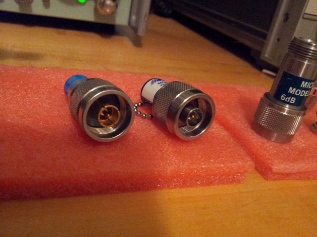
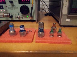
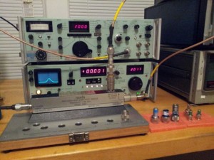
The warriors: Left to right-items 1 to 5
20140827_210752

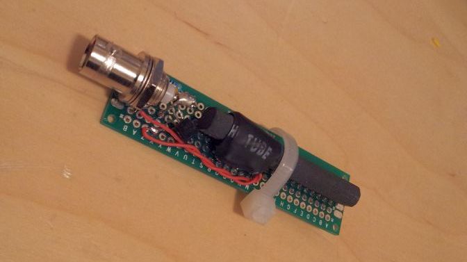
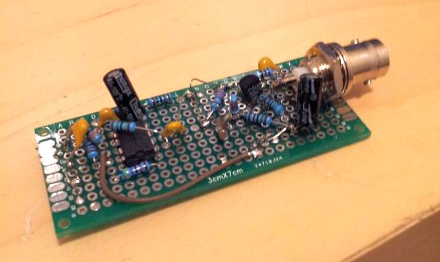
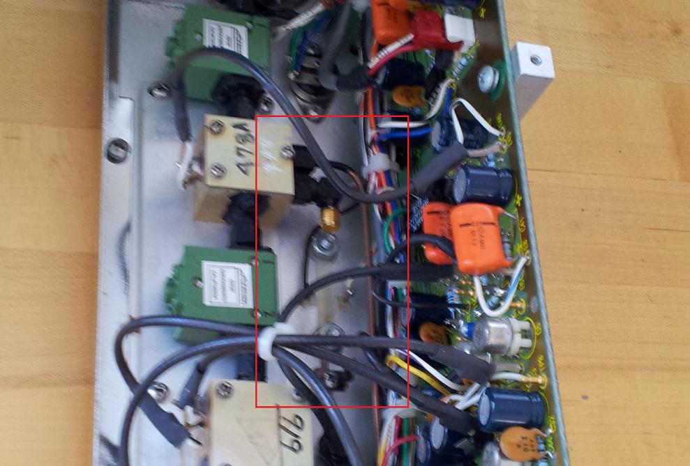
The test setup: Micro-Tel SG-811 Signal Source, Micro-Tel 1295 Precision Attenuation Measurement Receiver, Narda Precision High Directivity Bridge Model 5082, Narda APC-7 to N adapters.
20140827_211140

The test procedure: At each frequency, full reflection (open) is used to set the “0 dB” level. Return loss can then be measured directly as attenuation of the reflected signal, when the termination is attached to the test port. To determine the error limits of the SWR measurement, the directivity is known, the insertion loss of the bridge has been measured, and the attenuation measurement error itself (by the Micro-Tel 1295) is negligible.

Results
140827 swr of various terminations d0
140827 terminations data

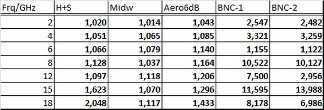
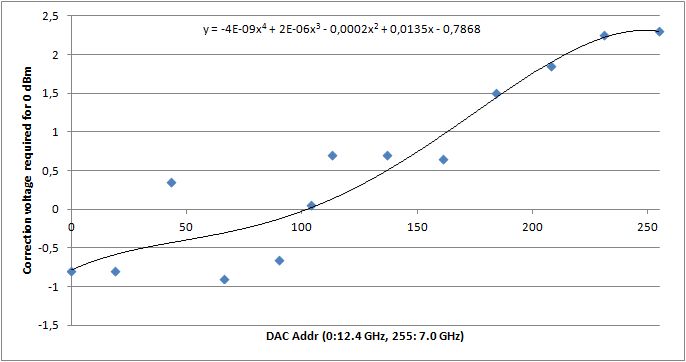
SWR vs. frequency, all terminations
140827 terminations1

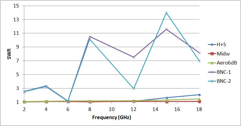
There are clearly two groups, the terminations made for GHz service, and the others – BNC, items (4) and (5), that were not. Interestingly enough, at 6 GHz, these terminations are more or less ideal, with SWR close to 1. So you can use these at exactly 6 GHz, and integer-multiples of 6 GHz, but still, I would suggest not to. They are also working great at DC, because of their “+-1%” accuracy which is mentioned on the label.

SWR vs. frequency, only the items (1) through (3)
140827 terminations2

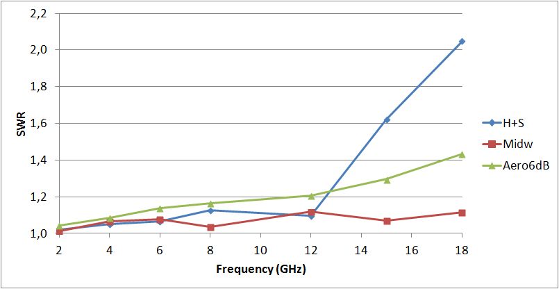
A closer look at the real performers – the Huber+Suhner, although only specified to 6 GHz is working well within its SWR max. 1.2@6 GHz specification, even considering the error limits of this measurement, and can be used up to 12 GHz, no problem.
The Midwest Microwave 2070 – I like this model very much, because of the rugged stainless steel construction (nothing gold-plated and fancy; you can get these for a few dollars, from surplus). It is way better than specified (SWR max. 1.25, measured: 1.12) – and, at 18 GHz, within the limits of the HPAK 909F Precision Coaxial Termination, intended as calibration standard, and listed for close to 1 k$.

A little hint – how to distinguish really high frequency N-type parts (18 GHz), from regular, say, several GHz (below 12 GHz) parts: the shield of the “precision” N-type connector is a non-slotted (see picture-right termination), where as the regular N connectors have a slotted shield, typically, 4 slots (see picture-left termination):
20140827_210812

DCF77 – Tell me, how far do these waves travel?

For those of you who don’t know, Germany has a time signal and frequency standard station, a 77.5 kHz carrier, emitted at a place near Frankfurt. About 50 kW of power – enough to provide most of Western Europe with perfectly accurate time. Radio controlled clocks have become the de-facto standard, in most of these places, and are available for a few Euros, amazingly cheap.

While this is all common knowledge, it was definitely news to me that this signal can be picked up in the US, at least at the East Coast – New York area, where I currently reside. These news came from a very much trustworthy fellow German, just a few miles away – he carried a radio controlled alarm clock over from Germany. And one day it started receiving a signal, and set itself back to German time.

Definitely, time for some experimentation.

The setup:

(1) A well-tuned ferrite antenna (same as is used in alarm clocks), with a little J-FET preamp. Additionally, a long wire (about 10 m/30 ft), connected to the hot end of the tuned circuit.
(if you need a schematic, just ask, works with a J310 J-FET)
20140827_211541c

(2) A long coaxial cable to get the antenna out of near field interferences.

(3) A xtal filter and amplifier/driver – to provide adequate signal levels.
(if you need a schematic, just ask, uses a NPN transistor, and an OPA703 CMOS rail-to-rail opamp)
20140827_211619c

(4) Monitoring of the signal, via PC soundcard, and Spectrum Lab software.

Current status:

So far, not a trace of the 77.5 kHz carrier has been received, even using a most sensitive HPAK 3585A spectrum analyzer – maybe, I just need to wait for better propagation conditions, to get these long waves over the ocean.

To be continued…

Some little improvements…

Over the last days, more and more imagery has been received, with the NOAA satellites on their appointed rounds. A few things were found that might help you to get things working better:

(1) A high sample rate of the SDR (like 3.2 MSPS) is neither necessary, nor advantageous, in fact, I discovered this to be the main reason for some interrupted frames – the data is flowing via USB at 3.2 MSPS, but not all the time. Also, the S/N seems to be better, at lower sample rates, like 0.9 MSPS.

(2) The bandwidth. Provided that it is heated-up and left running, the little crystal in the SDR USB stick is actually pretty stable. I need to use a correction value of about 17 kHz at the 137 MHz frequency, but once entered, no need to change so far. Once the frequency is corrected, there is no need to set the FM bandwidth any wider than it needs to be, about 38 kHz seems to do the trick.

(3) Volume control. Easy to set, about 70% on the WXtoIMG works fine – I didn’t look at this too carefully at the start – make sure to re-adjust the volume after coming back from other tasks with the SDR USB stick.

NOAA-19 (2014-08-27)
noaa-19 140827

NOAA-15 (2014-08-27)
noaa-15 140827

Not quite perfect, but I can see improvement!

Leveler calibration PROM, now: EPROM

Fortunately, the manual of the Wavetek has some detail on the leveler correction PROM. Essentially, it is fed with 8 bits representing the frequency, 255 (0xff) for 7.0 GHz, 0 (0x00) for 12.4 GHz. For each of the 256 steps, it has a correction byte stored in a Texas Instruments TBP28L22N 256×8 PROM. This is programmed at the factory, to match each individual RF deck.

20140827_075737p

Getting this exact device and programming tools ready was out of question, some of these PROMS might still around, with datecodes of the 80s, but really not worth the effort and cost.

Step-by-step

Step (1) – A little test rig was set up, with the recently repaired HPAK 8904A as a DC source (can source -10 to +10 Volts, in very fine steps), and the DC voltage connected to the leveler correction control voltage line. The Wavetek is designed for servicability, and there is a nice jumper to disengage the actual level correction DAC, and the feed an external voltage instead. An EIP 545A was used as a frequency counter and power meter. Cable and EIP 545A power meter accuracy was tested with my best calibrated source at hand, and found to be within +-0.5 dB over the 7 to 12.4 GHz band.

Step (2) – Data were collected by setting the Wavetek to various frequencies, mostly in 0.5 GHz steps, and the control voltage was adjusted for the power meter to read about 0 dBm. The data were then used to calculate the coefficients of a forth degree polynomial, and converted to the 256×8 bit format. The Wavetek uses a DAC0800LCN DAC, and the output voltage (after the on-board opamp, a LM307N) was found to be very close to 10.00 V with 0xff input, and nearly -10.00 V, for 0x00.

wavetek 907 cal
wavetekcorr

Step (3) – The tricky part. How to get a replacement for the 28L22 PROM? There are mainly two choices, one option would be to use a little microcontroller, that can easily function as a pseudo-memory, or use something more permanent, in this case, an EPROM. I had some 2532 around, therefore, not much effort. Only a small fraction of the 2532 will be used, 2 kbit of a total of 32 kbit. What a waste!
Unfortunately, the 2532 isn’t close in size to the 28L22, nor are the pins arranged in a similar fashion – but this can be solved with a little adapter board, and a few wires. Not the most beautiful solution, but who cares, it works!

20140827_075707

Leveler – Missing part!

As it turns out, somebody must have opened up the Wavetek 907A before, and it is missing a crucial part – the detector, for the leveling circuit! Checked out with the manual – there used to be a 6 dB pad (to get better SWR for the detector), and a positive-type tunnel diode detector (SMA input, SMA output). Nothing I have around here surplus.

20140825_130103p

Wait – there is a spare HP Schottky negative-type detector around in a drawer back home in Germany, and coincidence allowed to have it carried over to the US. This litte device as SMA input, SMC output, and with a little SMC to SMA adapter, at least a mechanical fit.

A little mod will is required to get this going, changing the polarity of the input amplifier. No big deal:

20140827_075831

Next step – there are correction coefficients stored in the Wavetek (in ROM), to compensate for signal losses along the RF chain, and to keep the output calibrated. This will require some more thought, to be continued.

HPAK 8904A – Power supply repair

With the failed parts identified, we need a replacement for the FES8DT diodes: 200 V, 8 A, 0.95 V drop, 35 ns recovery time, 125 A surge current.

Something more rugged – because already on the datasheet, it says “Ultrafast, rugged” – what do you want more – are the BYV79E-200 diodes.
These are 200 V, 14 A, below 0.9 V drop, 30 ns, 150 A. These should last for another 20+ years, and come in the same packaging, SOD59, aka TO220AC.

20140827_080801

Fortunately, I had some spares around from other activities, but you know – the best source is not xbay, but just some junk switchmode supplies that should be sitting around in any good electronics workshop – these are always keepers, and have come in handy as a source for parts, for more urgent (commercially relevant) repair jobs, rather than for the HPAK 8904A…

For the 8904A – one important thing! Never short out the RAM backup power on the main board – you will need to go through an activation routine, otherwise, your instrument will be rendered non-working. Don’t now why HPAK didn’t use EEPROM at the time, maybe, these were not yet invented… Following the instructions in the user manual (Thank You, HPAK, for providing all these manuals free of charge on the web!!!), the backup battery was replaced with a new Lithium cell. In the end, it might be a good idea anyway, to open-up the case every 10 years, get the the dust out, and a new battery in.

With new Schottkys, new RAM backup, new serial (and new code), the instrument is now fully functional, option 001 and 002, and will provide good service, hopefully, for decades to come!

20140827_080447

Anyone with a broken 8904A – feel free to contact me!