This time, not really a repair, but an upgrade.
Every lab or repair shop dealing with really high frequency circuits needs one: a microwave counter. The EIP 54x series has certainly been (and still is) one of the workhorses of the industry. EIP is now Phase Matrix, still selling counters. But I guess, not an easy tasks – there are quite a few of the EIP counters around, and they do have some little issues with tantalum capacitors, etc, but all in all, the EIP counters are really marvelous instruments, rock solid.
The 545A:
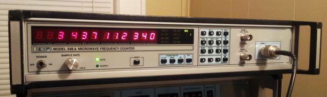
In my own shop, there are two 545A counters (18 GHz, N connector), and also a 548A, which is similar, but covers up to 26.5 GHz (3.5 mm connector). The 548A can go to frequencies as high as 110 GHz, with some external mixers. While these have provided good service over the years, they are all lacking ‘option 2’, the build-in power meter. At microwave frequencies, having a combined power meter and counter has a considerable advantage – no need for changing cables, no need for splitters or couplers – just the push of a button. And not always do you want to connect a circuit under test to a valuable 18 GHz+ spectrum analyzer or measurement receiver…
Fortunately, there are clever people around, at the Green Bay Professional Packet Radio club (“GBPPR”), which kindly provide the ROM images and some circuit modification info on the web – to convert a regular 545A, to an option 2 545A!
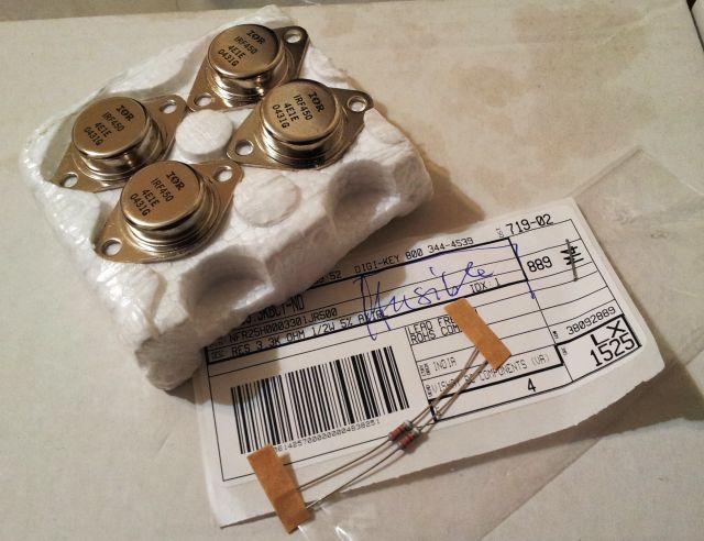
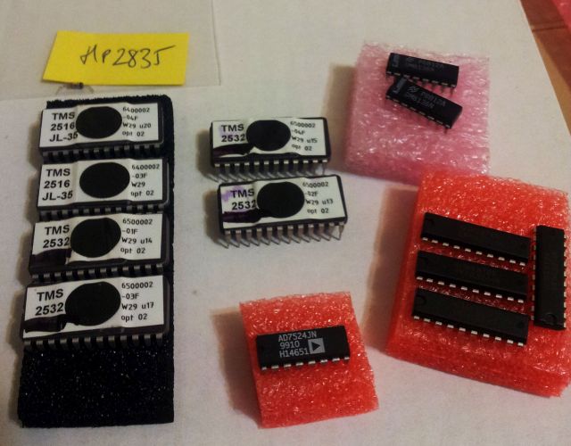
Well, first we need to collect some parts, a low capacity Schottky diode (HP 5082-2835, 1 pF max.; original EIP circuit uses a different kind, but really any low capacity Schottky will work), a DM8136N (a comparator/address decoder), a 74LS244 buffer, and an AD7524JN (8 bit DAC) – plus, a 10k resistor. Except for the DM8136N, nothing uncommon at all.
The only tricky part, at least here – the 2532 EPROMs. These aren’t accepted by any of the programmers around, and they need a high programming voltage. So first, put together a little programmer that attaches to an ATmega32L, and with the data transfered by USB.

It’s really crude – I don’t anticipate a lot more 2532 EPROMs that need programming, except for the EIP….
I had some 2532A around which are working perfectly fine, just lower programming voltage. The 2532A/2532 – they can be handled by some 2732 programmers, for reading the contents, with a little socket adapter (2532 and 2732 have different pinouts!) – but strangle, the same programmer doesn’t work for writing to the these old beasts.
The second type, they are 2516 EPROMs, no problem with a 2716 programmer.
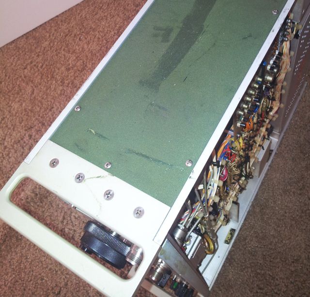
After fiddling around with the EPROMs, the little programmer, the adapter sockets – a few hours later – that’s now the set of parts:
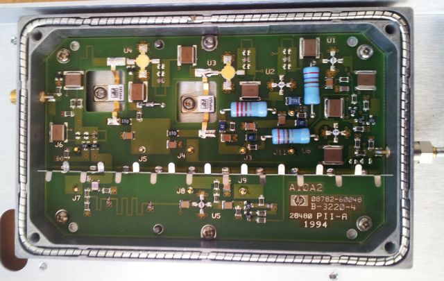
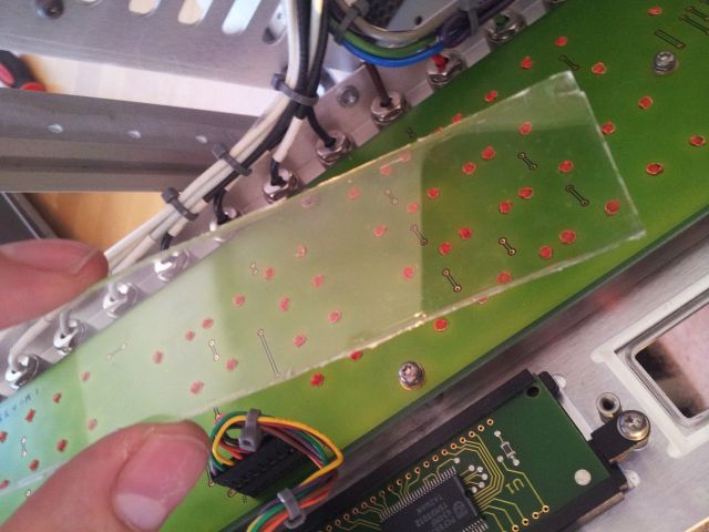
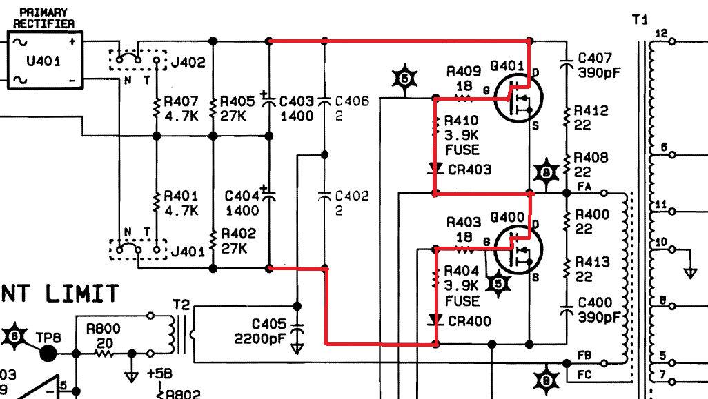
These are the boards, A105 and A107, with the parts installed – red rectangles: additional parts; yellow: removed parts (resistors R39 and R40).
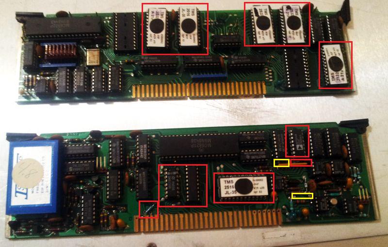
I would suggest to put all parts in sockets, like EIP did. Then you can change your counter back, to non-option 2, should you ever want to.
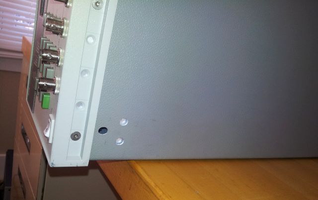
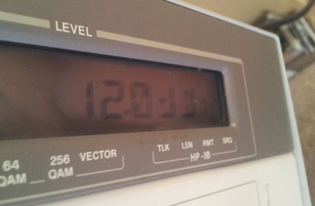
After a bit of soldering – that what we have – a working option 2 EIP 545A.
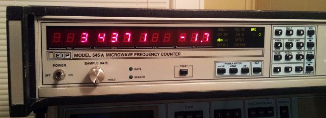
The power meter can be switched off – if you need the extra digits. Typically, I don’t.
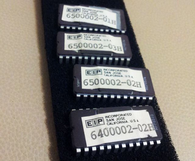
All that is left are the original EIP EPROMs, programmed in San Jose, California. Collectables.
Any questions, please let me know!