Cheap personal scales: turned into parcel scales with USB interface

With many parcels being shipped, and for some other projects including measuring the contents and consumption of LPG gas cyliners, other gas cylinders, chemical tanks etc, I always wanted a slim and stable balance, at low cost. Sure we can fabricate one from steel plates and load cells, at considerable cost. But why not try with a personal scales, and convert it to some usable tool. This scales from local LIDL supermarket comes for EUR 8.99 in the shop, 10 dollars.

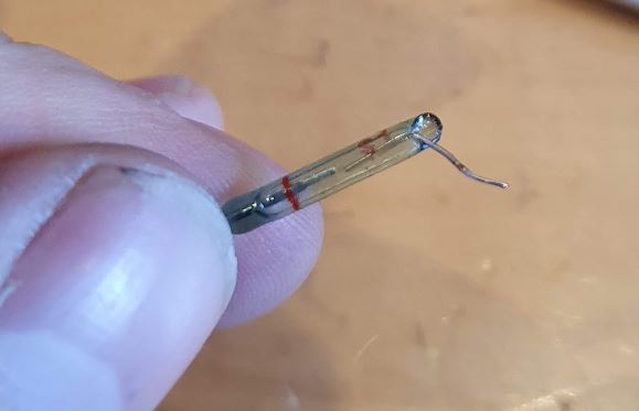
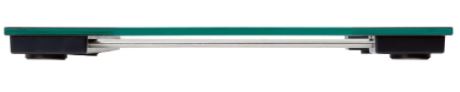
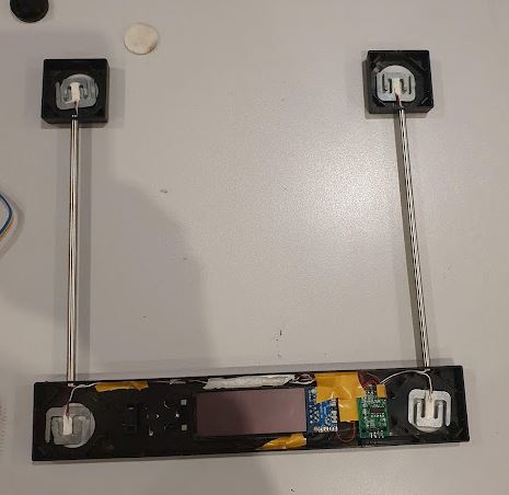
It is very slim and stable, basically a piece of hardened glass, with 4 load cells. There are 2 thin-walled stainless tubes to carry the wires to the main processor.

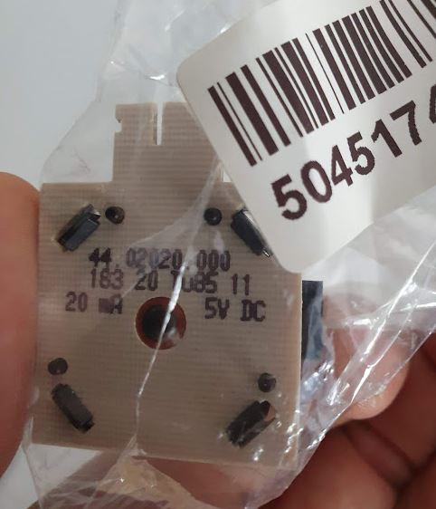
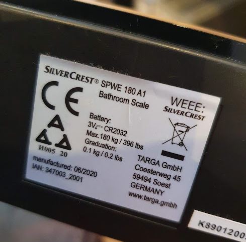
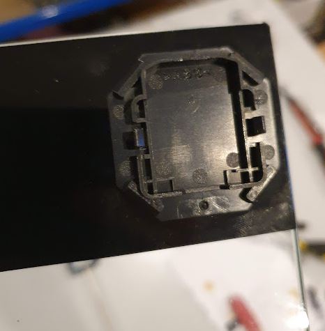
That’s the type, just for reference:

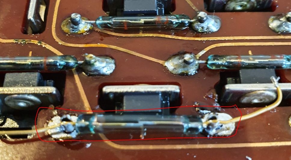
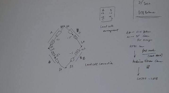
The load cells are the typical 3-wire elements (two load elements inside, red is the center).

The main disadvantage of these balances is (in addition to the absence of an interface) the absence of a continuous reading, in contrast to a good old analog balance it only shows one weight once, when you step on it. For various uses, I rather need a balance that continuously shows the weight, and can transfer it to a host for data analysis.

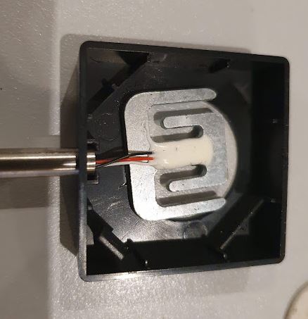
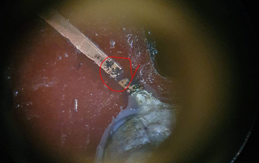
The load cells rest on certain plastic parts that are glued to the glass plate.

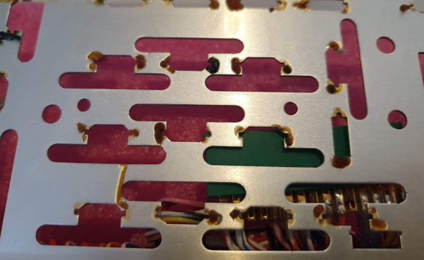
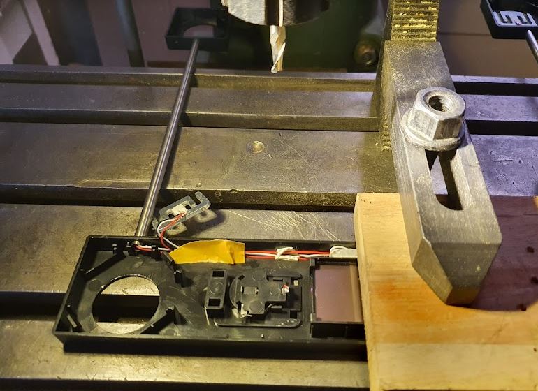
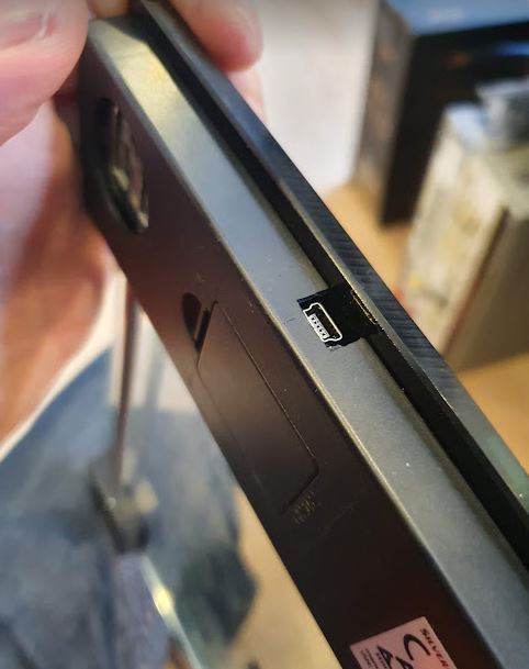
We need to cut a little modification on the milling machine, to make space for a small AVR controller board, and the USB (micro-USB) plug. There is no need to batteries any more, it will all be powered by USB.

For the load cell interface, the 4 load cells need to be wired up in a bridge (not important in which order of the load cells, but always white-while black-black, and alternating red wired for drive and signal inputs.

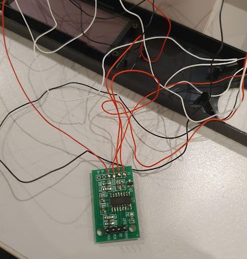
So we use a very common HX711 driver, it seems to work well with these load cells. I still had a board with higher data output rate (can be changed by floating a pin on the HX711), but you may select the data rate as you like. The HX711 is continuously active, and sending data to the host though a USB serial chip, CH340.

The internals, a arduino nano fake board (not running arduino code, but just some plain avr-gcc code), and the HX711 all wired up, we just need some hot glue to keep it together.

All ready to be put back together. Watch the wires, these are very thin.

The USB port, it all looks as if it had never been without.

The receiver side, the balance digital converted value is directly transmitted to the host, so all the conversion to kg and zero correction is done by the host, including smoothing.

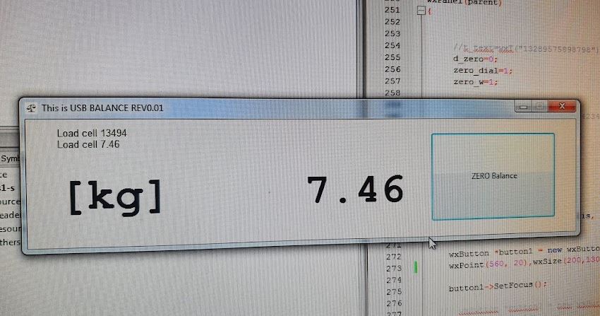
It is just a simple software, I programmed it using wxWidgets, but you can use any software that can handle USB/RS-232 communication and read serial ports, including Python, etc.

One bug with Windows – because of the continuous data stream over serial, Windows 7 seems to believe the balance is a serial mouse, and starts randomly moving the mouse pointer. With the little code below, this can be disabled and avoided. Probably need to add some waiting time before transmission starts in the AVR code.

If you need any of the code or further instructions, just let me know!

For calibration, a good hint, you can use milk packages (UHT milk), one pack is about 1060 g with very little variance, and it can easily be stacked up.
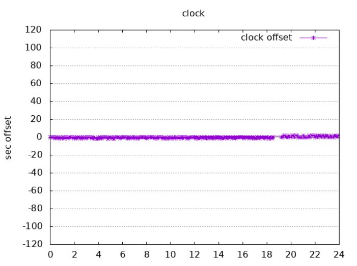
The Zero-Point seems to be very stable, I tested it after 90 kg load changes and so on, and it is not moving by 10 g.

CNC Lathe Signal Conditioning: fighting the noise

For the control of my CNC lathe, I need to read the spindle encoder (index and rotation signal), and two glass scales. These encoders all provide TTL level signals, and so far it worked well, but there are cases were electric noise of the switching motor or other equipment in the workshop. So finally I decided to put a bit more effort and upgrade the interface.

So far, it is just a cable that connects the three sources (spindle-index, x, z) to a parallel port input (a PCI card).

For signal conditioning, the input signals are filtered with a 4n7 capacitor+330 R, followed by a 74LS14 inverter schmitt trigger.

Everything on a little PCB, and put in dust-proof case so that it will work in the dusty workshop.

Finally, put it to a test and it worked “out-of-the-box”.

A simple schematic:

Electronic Master Clock: a huge train station clock is ticking again

Recently, I have been asked how an old slave clock could be controlled, it was saved from being scrapped, when a local train station closed down. It is really big and heavy. Eventually, I checked it out and it can be operated from 12 V, 24 V, or higher voltages by adding a resistor. We decided to operate it on 12 V, simply because one of the slides (this is two-sided slave clock) had already been set to this value.

In order to control the slave clock, we have to send a 1~2 second long voltage pulse, every minute, in alternating polarity. Then the minute hand will advance minute by minute. There is no second hand on this slave clock.

The control board is fairly simple, to test it all out, I soldered it on a piece of prototype board. Main control is by an ATMEGA8 microcontroller. This is using its own clock, from a Kyocera HC1 crystal oscillator to derive a 1 minute time interval, and and auxiliary 1 second output, for calibration purposes.

The actual adjustment of the clock is done in software, because the oscillator is pretty stable, and this is just a test circuit. If the slave clock will be a minute off, or two, nobody will mind.

The clock drive is completely separate from the controller, isolated by optocouplers. I used a small transformer, with dual 12 V output (because it is small current only, the output voltage is high enough, but you may use a 15 V transformer if it is handy).

Seems we are about 25 ppm out. After correction, the clock was running well within 1 ppm, fractions of a second per day.

To make the contraption a safe and useful thing, I put it in a little box, with some cables and feed-throughs.
Now it is up for some long term test, let’s see if it needs any modification.

SMEG CS19ID-6 Range: another defect

It seems my SMEG kitchen range is getting older… at least it is again showing some issues. The right hand side front induction field is sometimes coming on, intermittently, only to shut off quickly again. Normal operation is no problem, but when it is switched off, it doesn’t remain fully switched off all the time. Could be dangerous if some pot is left on the induction field, and the range decides to switch it on by itself… a praise to all the old-fashioned switches that completely took power off the appliance.

First we need to find out the source of the issue, is the it controls electronics, or the switch? To test, I opened up the front panel (easy enough, it is just 8 screws…), and switched the cables going to two of the front panel switches. And, as it turns out, the issue also switched. So it is probably a defective switch rather than any issue with the electronics. That’s good news.

For about 35 EUR, I got a new switch, as it turns out, it is no switch put a potentiometer…

… and a quick exchange fixed the issue. Now let’s do some study of the old part.

Made by printing some conductive composite on a circuit board. Looking good. I can’t see any issue with it even under the microscope. Maybe just some contact issue, the contacts also don’t look clean.

So I will clean it all up thoroughly, bent the contacts a bit to give it slightly more force, and keep it as a spare.

These potentiometers aren’t cheap, at least the use good engineering plastics for it, like, glass fiber reinforced materials.

Siemens Master Clock: Revision 2

This clock has now been in my possession for close to 10 years, it is a Siemens master clock with 3/4 invar pendulum. It is a nice clock, but also needs some repairs at times, especially, the contact wear out or get dirty over time so every two or three year it needs adjustment, cleaning and so on. Another issue is the noise every minute, which is caused by an electromagnet driving the winding mechanism.

There are many contacts and all these need to work, also the main gear of the second hand is triggering a contact, which is known to have an adverse effect on the clock stability, by putting extra load (losses) on the pendulum.

So, we have to re-configure the winding mechanism, and I decided to use a maintenance-free stepper driver. Like those used in old floppy disk drivers.

Only needed to fabricate a metal bracket to mount it to the clockworks. Needless to say, no modification of the clock has been made, I just made use of the existing holes and screws.

To indicate the fully-wound position of the clock, there is normally another set of two contacts that stop the magnet from further winding up the clock. However, also these need some cleaning and adjustment at times, so I replaced them with a inductive proximity sensor.

The sensor has a M8x1 thread, so a mounting bracket can be easily fabricated from some brass.

To control the stepper motor, the winding mechanism, and the second’s pick up (a simple light gate with some comparator circuit), a electronics board is in place, using an ESP32 microcontroller that include a WLAN interface.

The circuit is fairly straightforward. The stepper is driven by a 4-phase uni-polar driver, which has some resistors and diodes, and current switched by darlington transistors. The current per phase is roughly 120 mA, and only one phase active per step, operating in full-step mode with 200 steps/rev. Timing is roughly 10 ms per step.

Power is obtained from 9 VAC power, but the circuit will accept DC or AC, any polarity. A DS18B20 is used for temperature sensing. I am thinking about adding a BMP180 barometric sensor to the circuit, but now that everything is running nicely, I don’t want to disturb the clock. In any case, the circuit is connected to the clock by a 15-pin SUB-D plug, so it can be removed from the clock without removing the dials or anything else.

So I can run a small web interface which is polled every 10 minutes by my main server, to get the current time deviation of the clock, and its temperature.

The adjustments were very easy, and it only took a day to get the clock working to within 1 sec/day deviation. Let’s see if there is some drift developing over time.

The software gave me quite a hard time initially, because the motor control is interacting with the pick up of the pendulum (the light gate signal wire and the motor wires with inductive currents all installed parallel and powered from the same supply, so there were some false counts. Now the timing is such that the winding happens in the dead time, i.e., after a “tick” of the pendulum, and well within the time to the next “tick” (tick-tock-tick-tock spaced 0.75 seconds, so it is 40 ticks per minute for the 3/4 pendulum). That solved the false-count issues altogether, and still I am using a filter algorithm to reconstruct the action pendulum motions perfectly fine, even if one tick would be missed, etc.

A Japanese hot pot: A hot spring without a hot spring

One of the most famous features of Japan is the availability of hot spring all around the country. If this is an advantage or disadvantage of my new living place in Germany remains yet to be seen, because the hot water close to the surface normally comes along with other earth activity including volcanos and earthquakes… Anyway, I have no source of hot water here other than by gas heating, so at least I wanted to have an outdoor bath resembling Japanese style.

The pot is handmade from high alumina clay, fired at about 1350°C, and shipped from famous Jingdezhen, Jiangxi China, within about 8 weeks. It is a heavy pot, about 350 kg. It resembles the Japanese made bath pots 1:1 but the price is much more competitive and a certain Ms. Wei of the pot company knows how to deal with foreign customers and can manage export of such items as a routine business… Transportation fees in Germany and customs duties, taxes turned out to be more costly than the pot itself.

The essential elements are, (1) the pot, (2) the piping system all made from DN40 glue-fitting PVC-U pipe, (3) a circulation pump (180 Watts, Wiltec 51554, including a filter/strainer), (4) a gas heater (fired by Propan), (5) hot water supply pipe – this is constructed such that it can be drained easily in winter after each use, so it is possible to have a bath also in freezing conditions, made from 18 mm copper pipe and fed by the main hot water system of the house (using natural gas), (6) a regulator system to keep stable temperature.

The water heater has a safety system to switch off the heater after 20 minutes of use, and it has a built-in electric ignition system powered by 2 batteries, 1.5 Volts each. In order to achieve temperature regulation without interfering with the internal circuit of the gas heater, I just switch on and off the 3 V power to the heater.

Normally the heater is only used to keep the water at constant temperature of about 42°C (Japanese baths are really hot…), which takes less than 20 min on-time, anyway, I decided to add a timer circuit that interrupts the heater ever 15 minutes for 30 seconds. So essentially, it can continuously heat the bath even when filling in cold water. Normally the bath is started with reasonably hot water from the house main supply.

Unfortunately, the ignition system by high voltage causes the regulator to hang up. The high voltage sparks change the ground potential it seems, and even some attempts with protection and clean-up circuits (low pass filters) had no permanent effect, when powered from a single supply that is split to 12 V the regulator/timer, and 3 V for the heater. So I now powder the unit from two completely separate powder adapters, and two completely separated circuits, isolated by mechanical relay.

The voltage regulator for 3 V is a simple LM317 circuit, with some more capacitors and features to protect it from any surge voltages.

The temperature regulator and timer, sure you could build it yourself with some microcontroller, display, etc, but no need as the complete module is available for less than 3 EUR mail-order.

The water circuit has the circulation pump. Note that not all the water is passing through the heat, only a certain portion, and pressure is generated by an orifice in parallel with the heater. Temperature sensing is done in the circulation loop. In winter the circulation system can be completely drained and switched-off by appropriate ball valves. So you can still have a bath, but you just can’t heat it by the circulation system (rather need to add more hot water, or just limit the bath to 1 hour or so).

The heat loss seems to be about 1 kW, so we need to run the heater that is using about 1.2-1.4 kg of propane per hour of operation only for some minutes at a time (1 kg propane has about 14 kWh of energy, and we may assume an efficiency of 0.7). Experience shows that is this correct, the heater may switch on every 15-20 minutes of so for about 3 minutes.

Now the system is completely automatic. In normal usage there is no need to adjust any regulators. Just fill in water and switch the bath main switch to “ON”.

Lastly, the water is not just plain tap water but sure enough I am adding bath salts composed such that they resemble my favorite Yamaguchi prefecture hot spring pretty well!

Olympia CD401 Tischrechner: a magnetic keyboard

This marvelous CD401 Nixie-Tube calculator came to me in pristine condition, from a friend, and including all the accessories and even the original power cord. Just that it has some small defects. Numbers 2 and 7 didn’t work, and some of the keys have mechanical issues. Noteworthy, this little calculator came from Japan, despite being branded Olympia (which is a German company no longer in existence), an made by Matsushita Electrics, also known as Panasonic, in the early 70s. It cost close to 1000 Deutschmarks, may be equivalent to a two week’s salary of an engineer at the time…

Someone had apparently tried to fix it before, using inappropriate tools and scratching some internals, and not taking care of proper alignment of the parts.

The non-reactive “2” could easily be traced by a continuity tester, a bad circuit trace (the grease seems to be slightly acidic and has some greenish discoloration in places – copper corrosion).

The trace would be easily fixed with a short wire and some solder. The other defect – maybe introduced by the earlier repair attempts, a broken reed switch. The keyboard as such is a remarkedly complex setup – each key has several metal and plastic parts, and a magnet that operates a reed switch. Clearly, this had been built to a certain standard of longevity at the time, an engineering tool rather than a “pocket calculator”.

I keep a box of reed switches as spares, so luckly found one that is a pretty exact fit of the original.

Some careful re-assembly, some cleaning of old grease, and the instrument can go for a test. Note that there is exposed mains voltage around the transformer – why didn’t they put some cover?? It is right open and exposed and will give you an electric shock when you touch it…

That’t finally the machine all fixed and in best working order, probably soon it will be 50 years old.

HP 3562A Signal Analyzer: a broken display and an easy fix

Recently, during some phase noise measurements, my 3562A failed. This instrument is an essential part of the noise test set, it is used for all frequency offsets up to 100 kHz, and as a signal/noise source (the 3562A has a fairly capable built-in noise source, signal source, etc.).
While the communication via GPIB went well and I could still complete the test job, the CRT went dark with no sign of life. I also have a second unit, with a LCD display, but the 3562A of the phase noise test set still has its original CRT. Let’s hope we can fix it because I don’t want to invest in a new LCD or anything for this purpose.

So I opened up the box (fortunately, it is accessible on top of the test set which is a stack of instruments, maybe 250 kgs of electronics), and did some checks. As it turns out, one of the rails of the CRT driver boards is down.

Some years back I had already replaced some tantalums, maybe some more of these have gone bad? So I cut some wires at suspicious capacitors – you can normally do this no problem, because the instrument will still function even with some buffer caps missing.

In fact, after the 3rd cut, the rail came back. The tantalum had a full short but no sign of smoke or heat, probably, because of various protection circuits of the power supply.

Replaced it with a similar electrolytic cap, probably this will do. It is a question of repair philosophy, should you replace all tantalums in such device, if you found two defective caps? I decided not to, because the fix every 5 years is easy enough, and there are just too many tantalums in it, moreover, I may break some contacts or cause issues with electrostatic discharge. For the current repair, I didn’t even remove the board, just cut the capacitor from the top and solder the spare back, from the top. As some old laser engineer told me once, the less you touch it, the better it will work. Sure enough, if the objective is to bring the unit back to the best state of reliability, it would be best just to replace the whole CRT by a new LCD assembly, or by a few 100 USD worth of KEMET high-rel tantalums and do a 5 hour solder and disassembly/assembly job…

HP 8569A Spectrum Analyzer: two mysterious resistors

Again, some repairs of a 8569A spectrum analyzer. This time, no problem at all with the front selectors and contacts that break all too often, but with the CRT showing only a defocused vertical line. Some probing around – the analyzer appears to be find but something wrong with the deflection circuit? This is on the A5 assembly, and with no extender board around, quite difficult to probe, and a bit dangerous because this assembly is using +120 VDC. Any short may damage the supply, and any touch may give you a shock. So better exercise some care. By soldering wires, I was able to trace the signal and it seemed to be OK up until to some of the last amplification stages of the X amplifier. Maybe something wrong with the transistors – no these are good. Probing around on the board, checking all values of components close-by: the 75k resistors (fairly large sized 0.5 Watt resistors) are high-resistance, both seemed to have failed at the same time – strange. Eventually, this is becoming a quite frequent failure, already the 5th case or so over the last few years of open high-ohmic, say, 100k and about, resistors that are subject to 100 V or similar “high voltage” usage.

With no suitable 75k resistors available, I went with a combination of 82k parallel to 880k, resulting in 75.01k, close enough. And the 82k resistors that need to carry most of the current are really good old low inductance transistors suitable for such 100 volts service.

The repair, it is not particularly beautiful, but it works and at no cost, with available parts. Finally, some hours of test to make sure there is nothing else at fault in this unit. All good, test passed.

Heating energy consumption: first evaluations, and total annual energy demand

In the meantime, I have collected enough consumption data for gas consumption (mostly heating, some little bits for hot water), and at various temperatures outdoors, including, very cold temperatures.

As it turns out, the gas consumption correlates well with the outside temperature (daily average temperature in 2 m height, as officially recorded close to my place by the weather authorities).

With datasets of daily temperatures for 2019 and 2020, we can then estimate the total gas consumption of these years.

The 2019 predicted consumption:

The 2020 predicted consumption:

For German standards, everything less than 100 kWh per m2 and year is quite reasonable. I need to admit that not all of the rooms are fully heated all the time, but well, it is not all that bad, comfortable, and affordable.

Here an energy rating chart – in German – around 100 is a good value, above 200 … there it is getting really bad, wasteful and expensive!

SimonsDialogs – A wild collection of random thoughts, observations and learnings. Presented by Simon.