
One of the shortcomings of these handy and cheap SDR USB sticks is the offset of the reference, and the drift. First, lets see what we have: in the meantime, I have two more or these little units to play around, and all have about 70-100 ppm offset, positive.
The reference is derived from a small 28.8 MHz crystal, and while such crystals are pretty much suitable for clock generation, they do drift with temperature, and the SDR USB stick is getting hot during use… Quick look inside (case can be easily opened, no damage):
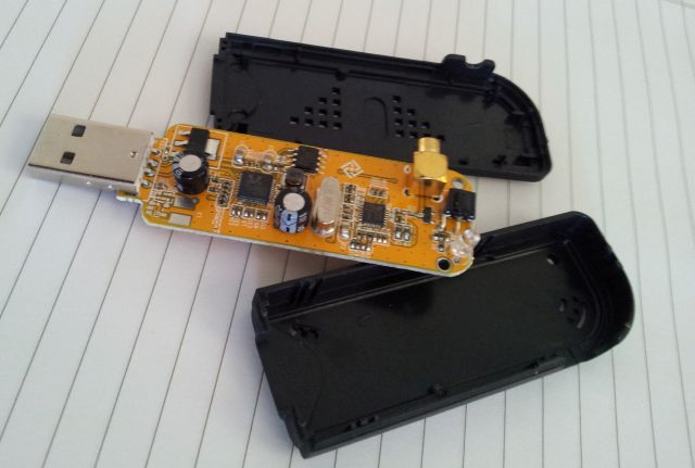
The small silvery metal can is the crystal. Any temperature change will cause this to slightly change frequency.
So, what about the crystal drift? Easy enough, just hooked up one of the sticks to a counter (with stable timebase; you need to use high impedance probe, otherwise, proble will pull the crystal frequency), and logged the frequency values for an hour, after “cold” startup (stick with no case).
The result:
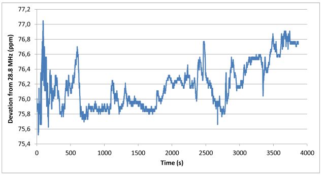
1 to 2 ppm, that’s not all that bad! Still, in the world of precision oscillators, it’s ridiculously drifting. So for any precise characterization of the SDR USB device, we need to get this under control. Some have tried to replace the crystal by a TCXO, but even with this, it will be challenging to break the 1 ppm (1 kHz at 1 GHz!) mark.
A quick look at the datasheets reveals that pins 8 and 9 of the R820T are the input/output of the xtal drive circuit, and pin 10 forward the clock signal to the RTL2832U, to safe some parts, and cost.
That’s how the oscillator output looks like, probed at pin 9, with a 10 Meg probe (0.5 V/div, 10 ns/div)
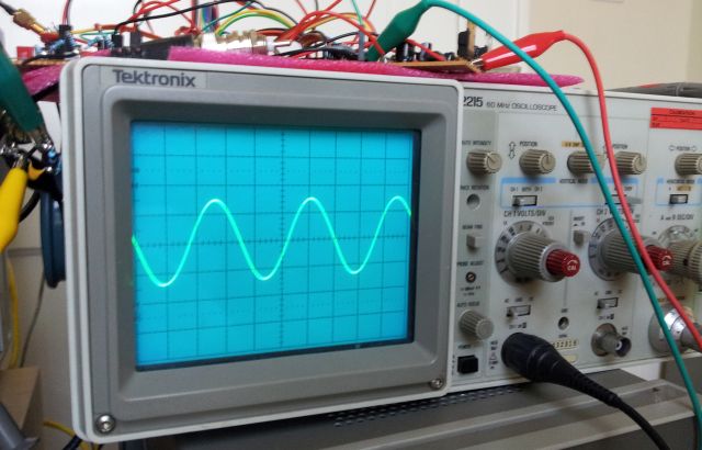
The signal, amplitude is about 1.5 Vpp, with a DC bias of 1.2 V.
Therefore, if we want to substitute the crystal, we have to feed a few dBms of power at 28.8 MHz into pin 8, and leave pin 9 unconnected. The feed line (50 Ohms) requires some adequate termination. We also need to provide a DC block, with a little coupling capacitor.
That’s the little hack:
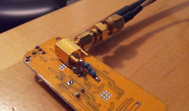
A SMC connector, terminated with 82 Ohm (which will be in parallel with the impedance of the R820T, hopefully giving about 50 Ohm, or close enough), and with 0805 10 nF capacitor, connected to pin 8 of the R820T.
As for the new reference source – nothing less than a HPAK 8662A, which is a real marvel of engineering and one of the best sources I can suggest for any tests that require low phase noise close to the carrier. It is stable to better than 0.0005 ppm, per day – compare this to the 1 ppm, per hour…..
Sure, not the mention – the 8662a carries 80 pounds of electronics, a big fan, and uses about 300 Watts of power to keep things clean.
The new clock source for the SDR USB stick:

The reference level needed to drive to R820T oscillator – just by trial and error, things start to work at about 400 mV, and up to 1 V of signal doesn’t seem to change anything. So I set the level to 500 mV into 50 Ohm, and this seems to work well.
Interestingly, the R820 T seems to work from about 28.75 to 28.85 MHz reference, with no change in performance (at least nothing obvious), except, of course, for the frequency shift. At frequencies below about 28.72, and above 28.89, the stick crashes-no more data comming.
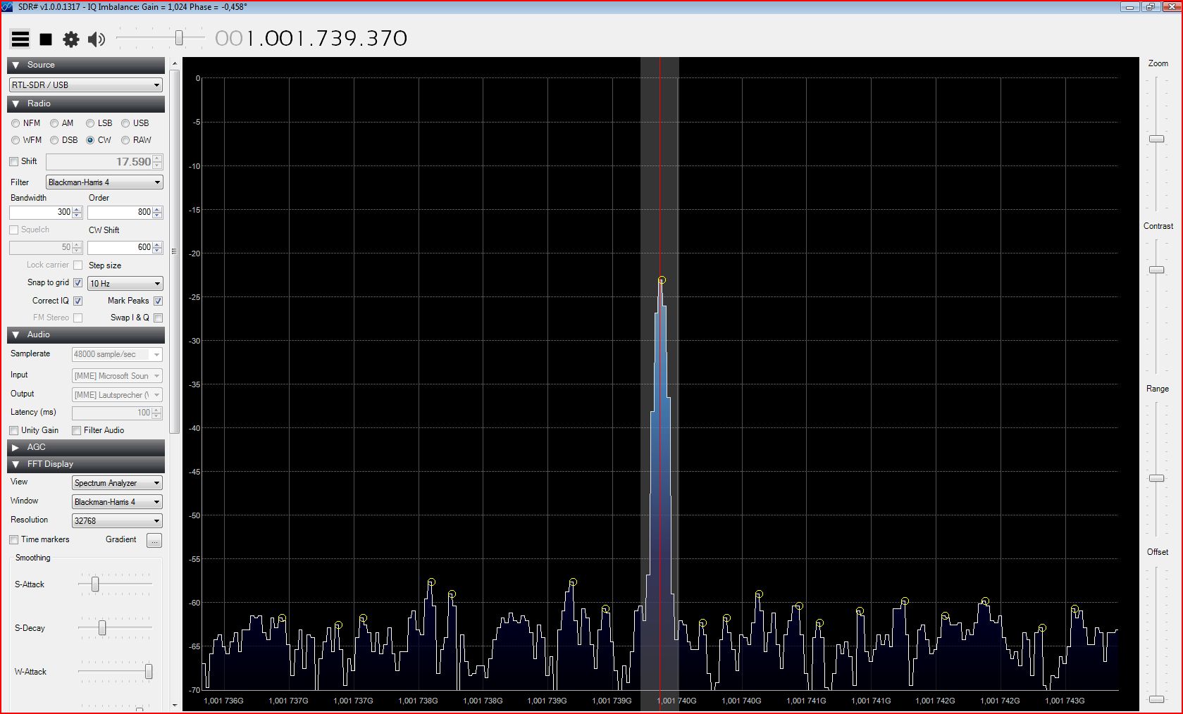
Some tests: 28.800 MHz reference, 1 GHz signal (note the small frequency shift, which is related to SDRSharp software, not to any hardware offsets)

28.75 MHz reference – still 1 GHz signal
28.85 MHz reference – still 1 GHz signal

Checking the math, this all makes sense – for 28.75 MHz, a reading of 1001.739 MHz would be expected, and 998.267, for the 28.85 MHz reference.