
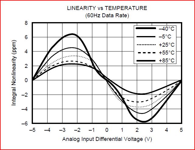
After putting a bit more thought into this, let’s have a look again at the kind of nonlinearity observed for the ADS1211. We only know three points where there will be no error due to non-linearity: the zero point (because that will be covered by the zero point calibration), and the plus (and minus) voltage, at which the gain calibration is carrier out. The gain will be calibrated both for the positive and negative direction, simply by reversing the same calibration voltage, most likely, about 7.x volts, supplied by a LTZ1000.
Again, from the datasheet:
Now, what if we measure not just with one ADC, but with two, of the same kind, and hopefully, with the same non-linearity, but, with the polarity reversed. I.e., because of the fully differential nature, we can measure, simultaneously, the same voltage, both in the positive and negative direction. Doing this adequately should cancel out most of the (integral) nonlinearity. Furthermore, if use two independent references, for the two ADC we will also gain noise margin – because some of the noise in non-correlated and will cancel out – also, we will acquire the same signal independently, and do the averaging digitally! For non-correlated noise, this means about 3 dB gain, about half a bit!
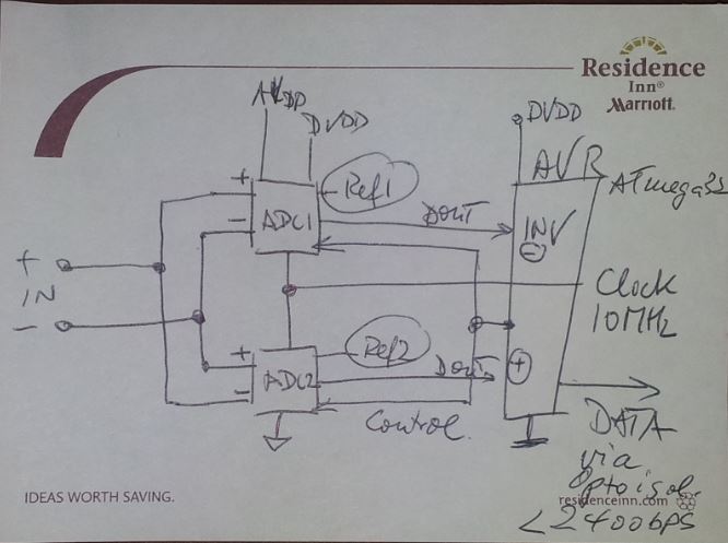
It only means that finally, we will need to put in 8 ADCs to measure two voltages, but, well, who cares – the given application can handle this, specialized equipment, and no relation to the total cost. And, with some luck, it will result in linearity errors of better than 1 ppm, and 7 digits resolution, with pretty fast data rates.
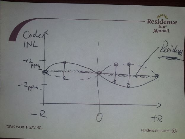
The solid line: non-linearity of ADC1, the dashed line – non-linearity of ADC2, both ADC are running fully synchronized, same control codes to both ADCs. Two digital outputs – and, one output will be fully inversed, directly in the ADC controller (an ATmega32L), to yield the average of the ADC1 reading, and the complementary of ADC2. Sure the difference to 0 V can also be analyzed, to check how far off the individual values are.
The ATmega32L will also do some decimation, from 60 Hz, to maybe 5 Hz or 1 Hz (independent of the mains frequency), and sent the data to the main controlled, via an optoelectronic isolator (the full ADC section design with fully floating digital and analog grounds). 1200 or 2400 baud will be plenty to get the data out. 60 Hz 6 bytes would be 360 bytes per second, about 3600 baud (need to count start and stop bit), but with decimation, we don’t need any fast couplers, etc.
Sure, this is currently an idea, and will need a closer look, but I assume, it will do the trick, at reasonable cost.
If it works out, maybe we go one step back in the final implementation – the ADS1211 has a 4 to 1 MUX, and rather than sampling simultaneously – we might just give up the noise advantage, and sample consecutively, once with positive polarity, and then, via another channel, in inverse polarity. But hey, Texas Instruments will be happy to sell a few more ADCs.
Finally, not sure if it is better to run both ADC from the same 10 MHz clock, or from separate clocks – some of the jitter induced noise might average out only, if the jitter sources are independent. So many, option, but quite easy to find out!