The MSR-904A has a remote control interface, to control most of the front panel settings by TTL level signals – operation mode, band, filters, IF attenuator, detector. All in all, 22 signal lines are needed.
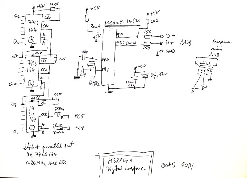
The circuit will also need provisions for latter addition of the PLL filter and PLL control – just a few digital lines. All will be controlled by a single USB interface.
First, we need a cable – the MSR-904A uses a DSUB-37 connector, but not all pins are used – so an adapter cable was fabricated to convert this to a much more common (and available) DSUB-25:
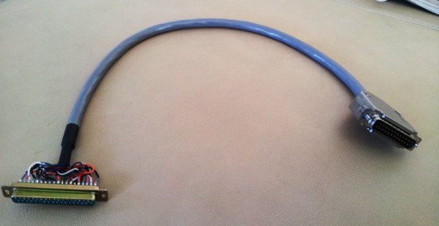
– quite a few wires!
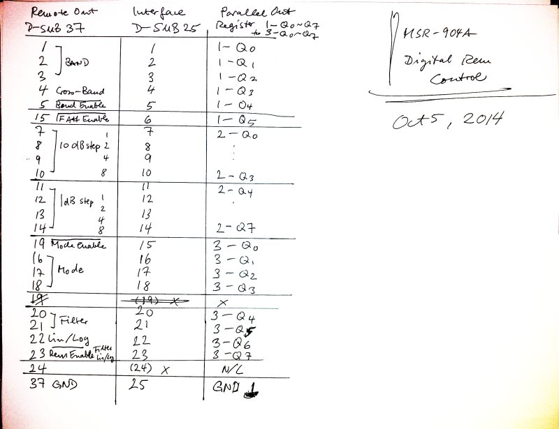
The digital control is implemented by a set of three 74LS164 shift registers, serial in, 8 bit out. These registers are very fast, can be set in a few microseconds. The three registers are named 1-Q0 (LSB of register 1) to 3-Q7 (MSB of register 3).
The micro is an ATmega8-16PU, running at 16 MHz – this has plenty of power to handle the USB interface, the digital control, and later, the PLL loop. There is also a standard 10 pin ISP header, not shown in the schematic.
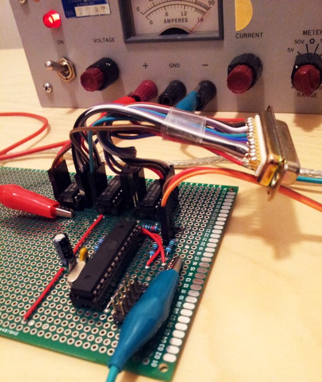
The circuit – build on a perfboard. No plans to fabricate a PCB, I don’t anticipate a big demand for MSR-904A remote control units, but still it should last many years. This is why a proper FR4 perfboard with plated-through holes is used.