
One of the shortcomings of the USB RTL SDR devices is the build-in oscillator. It is actually very stable and sufficient for all kinds of everyday uses, but I am using these SDR devices for narrowband applications, with down-converted microwave signals. So utmost frequency stability is a must.
Not only needs to frequency be stable, it is also a good idea lock all oscillators to a common reference, which typically is derived from a 10 MHz rubidium source (like in my lab), or a GPS-controlled VCXO.
How to get from 10 MHz to 28.8 MHz – well, not all that difficult, but needs quite a few parts. First, we need a circuit that can receive 10 Mhz signals, and clean them up and prepare them to be used by a PLL. Then, we need a VCXO (voltage controlled quarz oscillator) that can be tuned by the loop filter of the PLL to keep it at 28.8 MHz. The loop BW will be very very narrow, a few Hz at maximum. Comparator frequency can be up to 400 kHz, the largest common divider of 10000 and 28800; but I might select a value more like 100 kHz which can be readily derived from a 10 Mhz reference. There are plenty of programmable PLLs around, but I might just use a hardware solution here (only need to put together :288 and :100 dividers using some TTL logic).
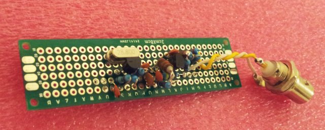
The circuit-
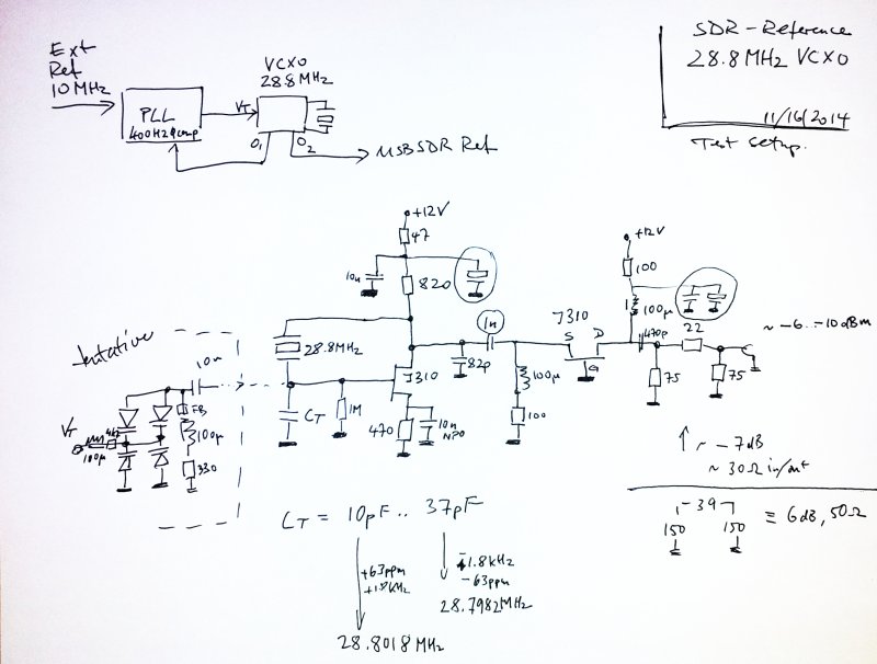
– nothing too fancy, and still needs some fine tuning. The xtal, it’s the original part de-soldered from the RTL SDR stick. These are actually pretty stable and well-behaved, at least for the devices I sourced from China.
The circuit employs a Pierce oscillator, build around a J310 FET. This is coupled into a common-bias amplifier, another J310, which provides the low output impedance. A matching network is added the make the circuit rather insensitive to changes in the load impedance. The circuits draws about 20 mA at 12 V. Not quite a power safer, hey, but this is not the objective here.
The items circled are just temporary parts, will need further optimization.
The big question – tuning range (pullability) of the xtal. Ideally, it should be a few 10s of ppm, to give the PLL some room to operate, and to account for aging effects over the years. Temperature-induced changes are on the order of a few ppm (see earlier post); but there is also drift, and other factors.
A quick test with some capacitors, and, stable oscillation can be found in a range of -1.8 to about 1.8 kHz around the 28.8 center frequency, this is quite satisfactory.
At the moment, still run with fixed capacitors, but I will add a varactor network to provide about 8 to 40 pF tuning capacity, by voltage input.
In an effort to keep phase noise down, I might employ a circuit used a lot for earlier projects, with anti-parallel varactor diodes.

The spectra look pretty clean, and the power is as expected, about -10..-6 dBm. I will use this output to drive the PLL, and add another amplifier to drive the RTL SDR R820T reference input – well shielded from everything else to avoid spurs from the divider and PLL circuits.
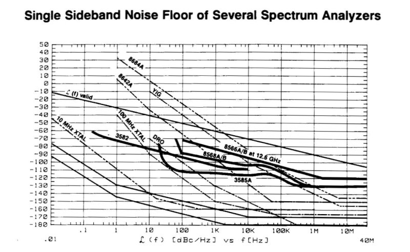
A quick test of the phase noise – hooked it up to a 3585A Spectrum Analyzer – there are some mains spurs, which will be reduced by adequate filtering once the circuit is fitted to a shielded box. Other than that, nothing really suspicious. All very close or at the noise floor of the 3585A.
One thought on “USB RTL SDR 28.8 MHz Reference: VCXO”