
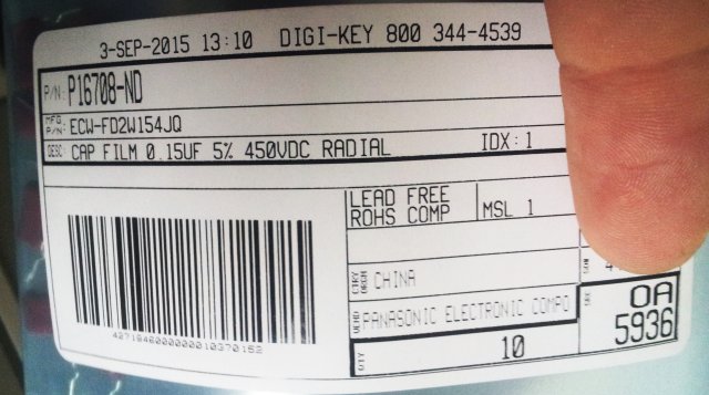
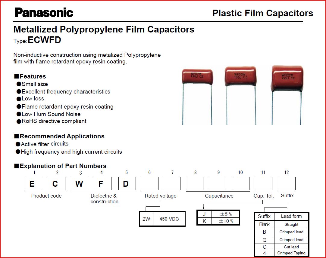
Finally, some capacitors arrived, Panasonic ECW FD type, polypropylene dielectric. These are very much suitable for any type of active filter or sample/hold circuits, thanks to their good capacitance stability, and low dielectric absorption.
Dielectric adsorption, not something specified on the datasheet. So I did a quick test, using a 50 Volt power supply, a 100 Ohms resistor, and a high-impendance (10 GOhm or more) voltmeter. Test follows this sequence:
(1) Charge capacitor for about 10 minutes; make sure to limit charge current to a few 10s of mA.
(2) Discharge for 10 seconds, using a 100 Ohm resistor.
(3) Measure voltage and record maximum value (V_measured) – typically, this takes several seconds.
(4) Calculate: V_measured/50 Volt *100%, the number obtained is a measure of dielectric absorption, in %.
Results: 0.005% for the ECW FD (Panasonic brand, PP dielectric), and 0.09% for the original cap, HEW-446 series (TRW brand, PET dielectric). Not bad, rule of thumb says that PP has 5x lower absorption than PET, well, but don’t quote me on the numbers measured – these are just rough estimates, fair enough. Needless to say, the new capacitors will outperform the original ones by far – and hopefully last as long, or longer, 30+ years….
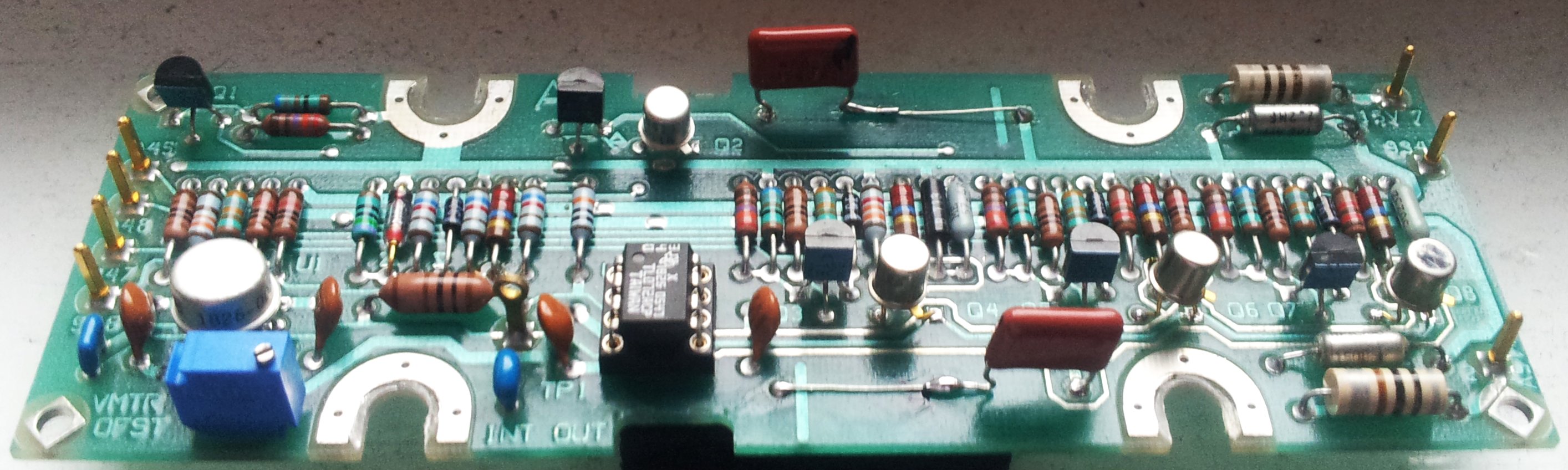
Another detail. Note the line on the top side of the A7 board, close to one terminal of the capacitor? This is the outer winding of the capacitive layer. This goes to ground. The ECW FD aren’t marked for their winding direction (these are non-polar caps, but still, there is an outer layer of foil, and an inner layer, and the outer layer does pick up more noise, and thus needs to go to the lower impedance connection). But the winding direction can easily be determined, just connect the capacitor to an oscilloscope probe, and hold the part between your fingers – then, swap the probe (switch ground and hot connection). You will see different levels of noise on the screen, mainly, 50/60 Hz hum. Select the connections for lowest noise, and the ground lead of the oscilloscope probe will then indicate the outer layer of the winding. Best, mark it with a felt pen.
Good day Mike Here ZL1BTB, I had a thought re calibration of noise sources with the HP8970 and since you have far more experience with the instrument than me Ill run this idea past you.
Why cant you use some precision rf attenuators eg 3db 6 db 10 db 20 db etc used between the rf in port and a noise source ‘ since the 8970 can display loss figures then one can fiddle around adjusting the “” ENR”” value in the calibration table manually until the gain display shows the correct value ie 6 db or what ever attenuator you use ….
this gives the correct ENR value at the frequency of testing ??
would that work ?? kind regards Mike ZL1BTB hp8970 opt 020
Hi Mike, you would need one known reference point to calibrate the ENR value, but otherwise, it should work to calibrate flatness of a noise source as you propose. Also keep in mind, the noise source needs to be calibrated to 18 GHz, but the 8970a can only receive up to 1.5 GHz, so, you would need to some other setup to calibrate the noise source for the higher frequencies.