With the 28.8 MHz VCO design established, all we need to move this project on are divers for the 28.8 MHz (VCO) and 10 MHz (Reference) signals, a slow-acting PLL, and some auxilliary circuitry to feed the 28.8 MHz back to the RTL SDR.
The 28.8 MHz and 10 MHz signals are AC coupled with about 1 kHz input impedance, this is quite common for any 10 MHz reference signal input (used for various kinds of test equipment). These signals are then amplified/limited by unbuffered inverters, 74HCU04. This is a very cost-effective and easy solution, the HCU04 has push-pull outputs, and input clamping diodes. Still, some clamp diodes have been added for the 10 MHz input, just in case.
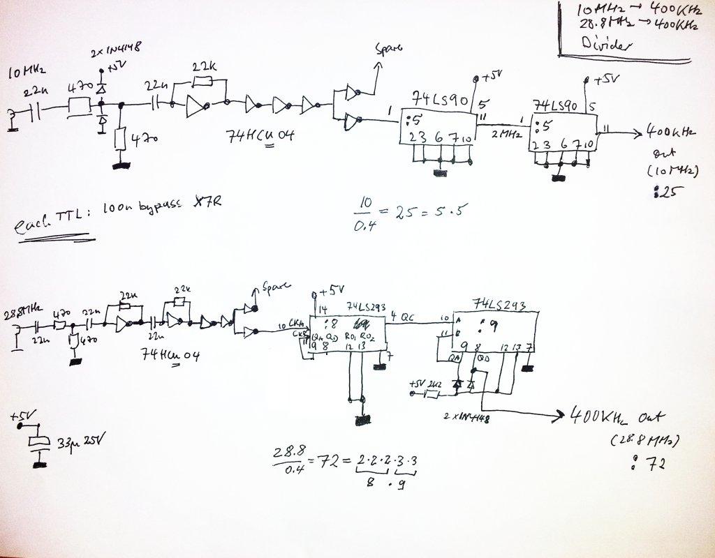
Looking at 28800 kHz, and 10000 kHz, 400 kHz is the largest common denominator. Accordingly, we need :72, and :25 division factors.
Division of the 10 MHz down to 400 kHz is accomplished by two 74LS90, but you can use other TTL decade dividers, these were just the circuits I had in stock.
28.8 to 400, a bit more tricky, first, divided by 8, using a 74LS293, and another LS293 that has two diodes, acting as an “OR”, to reset the counter when count 9 is reached.
Both 400 kHz signals are then compared use a flip-flop phase comparator, conveniently packaged in a 4046 PLL. For convenience, and to avoid digital noise on the 12 V rail powering the VCO, the 4046 is powered only from 5 V. This somehow limits the tuning output range, from close to 0 V, to about 3.1 V.
The loop filter is very slow acting, tens of seconds, because the objective of this PLL is to correct long-term drift of the 28.8 MHz reference, introduced by temperature, Xtal drift, etc., but otherwise not to impact its noise and oscillation characteristics.
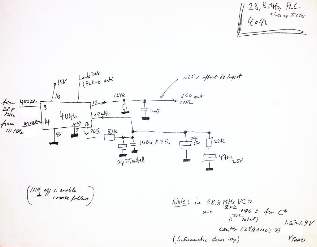
The VCO (see earlier post, VCO design) uses a fixed capacitor to set the tuning offset, this was changed to 4.4 pF, and finally to 2.2 pF, to properly center the tuning voltage (V_tune, output of the PLL loop filter buffer) within the 4046 output range, at roughly 1.7 V.
Extentensive testing was carried out the ensure that the VCO starts up properly, even if extreme V_tune voltages are applied; as the 28.8 MHz Xtals used in the USB RTL SDR devices may vary, you will need to check the required tuning range and pullability of the Xtal. Some Xtals oscillators will stop oscillating, if you pull to frequency up or down too much, which might happen during PLL start-up. This can lead to an undesirable lock-up condition.
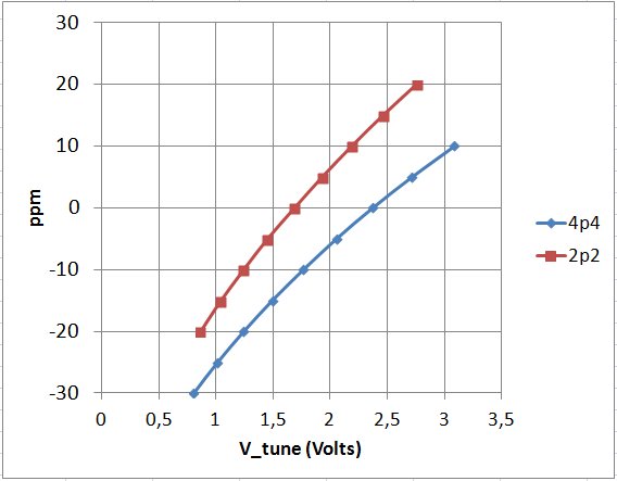
Here are the tuning characteristics, for 2p2, and 4p4 pF VCO capacitor values.
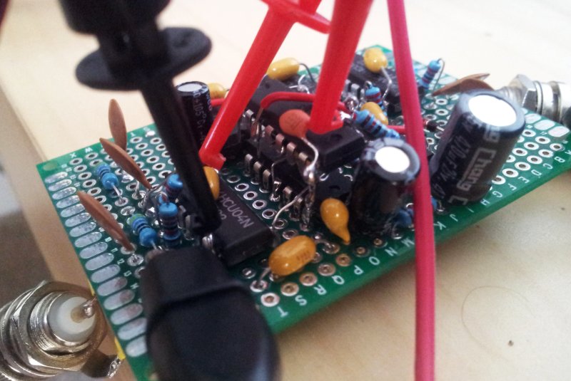
This is the divider and PLL board. Sure it would be much nicer to have everything completely separated, in shielded cans, etc., but I did not go to such effort. Later testing will reveal if it has any bad consequences for the 28.8 MHz phase noise, but so far, I don’t see much noise – will do a more in-depth comparison later.