
Winter approaching, all the pests of the world would like to hibernate in my attic. And around the house, an increasing number of squirrels is feeding off the birds’ food. But hold, for every problem, there is an electronic apparatus that can solve it, it this case: an ultrasonic pest chaser.
First of all, we need a random ultrasound signal generator. Tests have shown that frequencies in the 18 to 30 kHz range are best, and that not all animals respond to the same frequencies. So we need a cover-all solution. Furthermore, animals will get used to certain noises, even 105 dB ultrasonic noise. So we need to build-in some surprises. Sometimes, the machine will be quiet, then it will come up with all kinds of nasty sounds. Sure enough, at high level.
This is achieved by a little microprocessor, an AVR ATmega8, but you can use any micro of your choice. Please check out the source code – the sounds are generated by using certain pre-set sequences of breaks, durations and sound frequencies, and these are rotated in a repeated (but very long) pattern. The pattern won’t repeat to soon, because prime numbers have been chosen for the lengths of the sequences, thus, they appear almost random for the listener (only those with ears able to receive high frequency noises like this).
There is also a LED indicator signaling the ON state of the ultrasound. Even if you can’t hear it, please stay away from the speakers – these >100 dB may damage your hearing without any prior notice. Keep children away. As always, this post is for your education only, don’t try it at your home!!
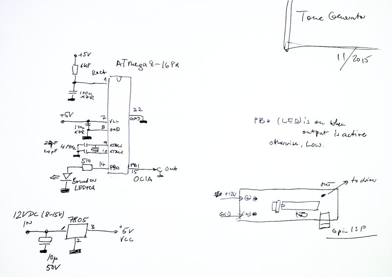
The signal generator schematic is as simple as it gets – frequency is derived from a 4 MHz crystal, via TIMER1 of an ATmega8. Some auxiliary circuitry is used to derive a 5 VDC rail from the supply voltage (anywhere from 10 to 30 V, depending on the speaker).
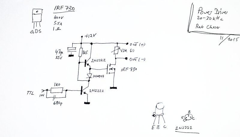
The power driver uses two NPN transistor and a MOSFET to provide sufficient current for the speaker. The speaker, some are under test, more about them later. Piezo high frequency speakers are the speaker of choice for this application.
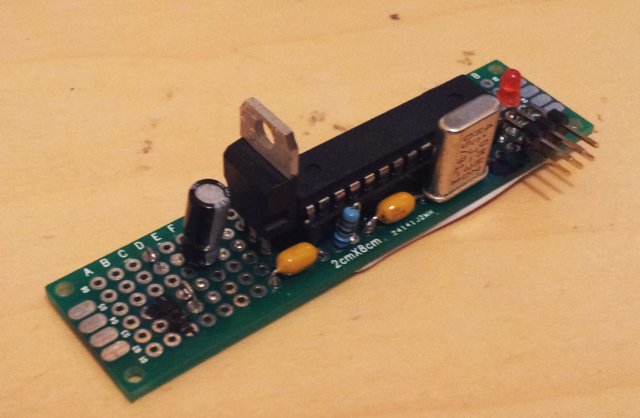
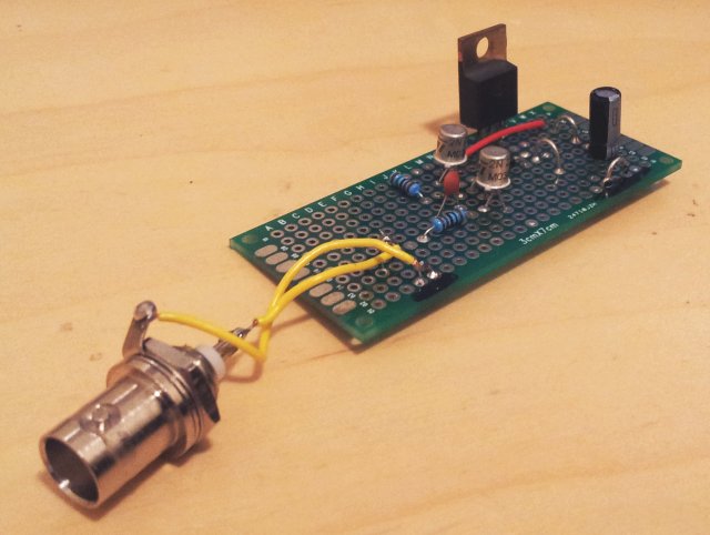
Some pictures of the boards – all build on plated-through FR4 perf board, this will last a long time even when use outside.
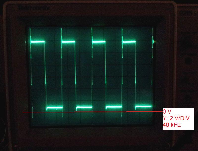
A test, using a 10 Ohm load resistor, and a 40 kHz drive signal. The MOSFET is switching nice and fast, no issues. For the speaker, it might help to couple the (capacitive) piezo with a suitable inductance, and to add a DC decoupling capacitor (about 1 µF, pulse resistant type). You can see that the resistance of the MOSFET in ON state is about 1 Ohm, current is about 1 Amp, for a 12 VDC supply voltage – and 0 V is one graticule up from the bottom of the scope.
Finally, a test of the circuit, frequency (Hz) vs. time (seconds). This nicely shows the “random” nature of the noise, with breaks of various lengths in between noise bursts. Poor squirrel, poor rat – but they have a choice: keep out of harm’s way, and out of the attic!

This is the microprocessor code, avrgcc.