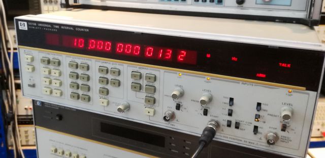
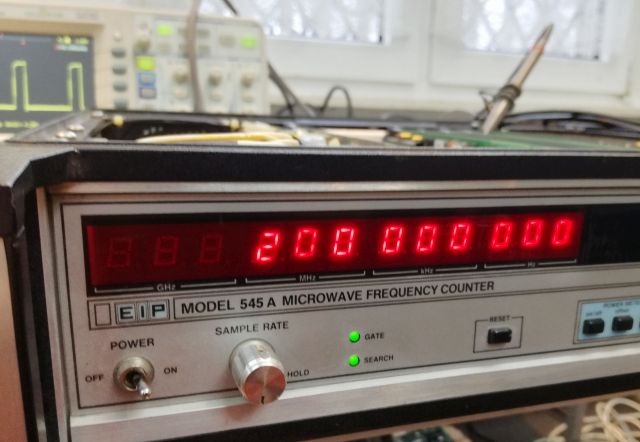
One more EIP 545A made it to my workshop, all in good shape, but not counting any microwaves, or other signals. The “gate” LED stays on permanently, and no counting also with the test function 01, which directs a 200 MHz signal to the counter chain.
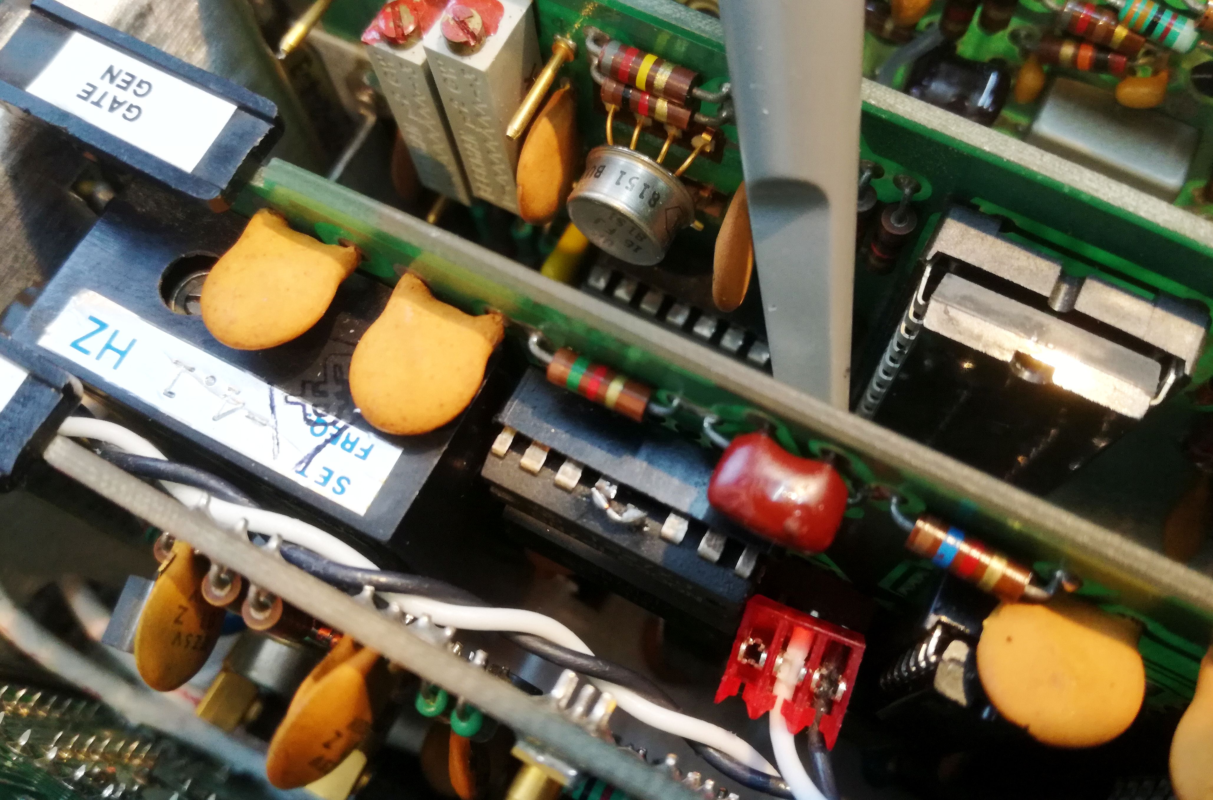
Looking at the schematics (fortunately, there is a full service manual available), the issue needs to be with the A107 gate generator assy. And, easy find, no 100 kHz signal present. So something must be wrong with the 10 MHz to 100 kHz divider. Soldered a wire to some of the signal points, and needed to go all the way back to pin 1 of the 1st divider, which is a decade counter. No signal present.
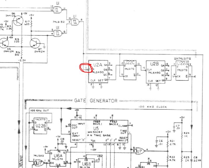
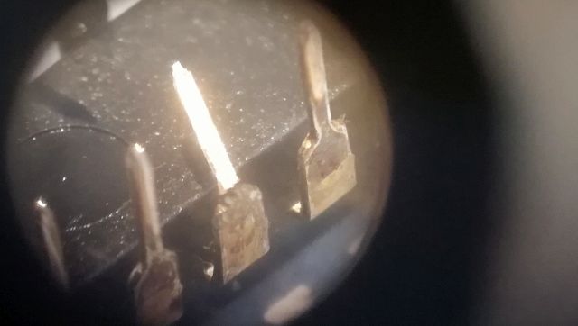
The EIP 545A has all-socketed ICs, so pulled the IC from the socket, and 1 leg missing! The leg number 1 that needs to take the 10 MHz and put it into the silicon chip. Temporarily soldered a wire onto the IC, and it solves the issue, but not a good permanent solution.
Also the other pins are very brittle, when you touch them, and bend a little bit, they break off, rather than bend. This is quite common for some old Texas Instrument TTL chips, not quite sure way – maybe some precipitation hardening of the copper material they used, or an interaction of the copper core with the tin/lead top layer. We don’t know, but it seems to be particularly common with El Salvador’s chips.
Here, a close-up of an (intentionally) broken leg.
Also the LS175 on the same board, although it was all good electrically, shows quite severe brittleness. I replaced with right away (with a 1977 date coded LS175, also from Texas Instruments!).
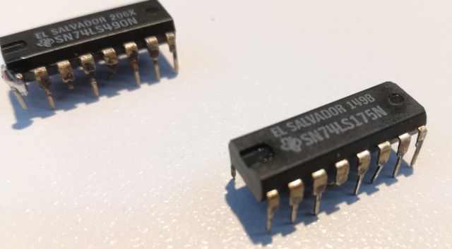
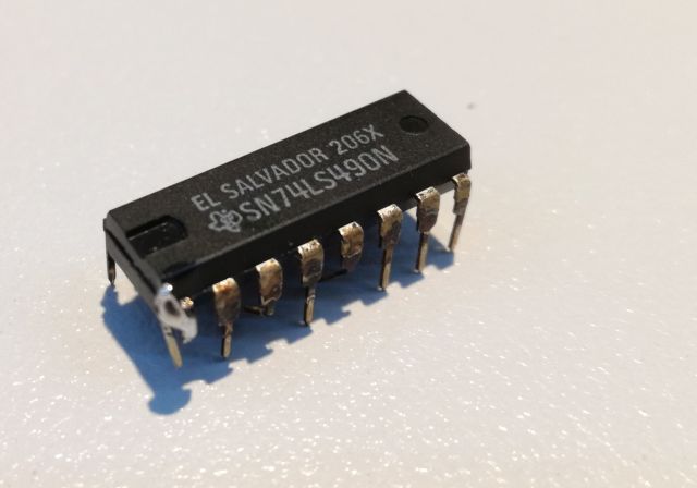
The LS490, unfortunately, none to be found in my basement storage of all kinds of electronics parts. Many counter TTLs, but no 490. An the offers, they are pretty pricey, and I want this instrument to be fixed today, rather than waiting days for some overprices NOS TTL ICs to be delivered.
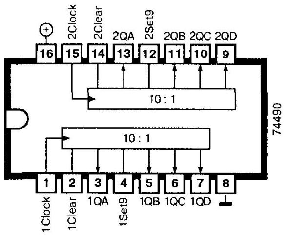
Looking at the datasheet, and schematic, it is a simple :10 divider, there are many of these – including the much more common LS390, and the pin arrangement is almost identical.
We only need to route the output of the 1st divider (a :2 divider) to the input of the next stage – and the LS390 will work like a LS490. The red lines show the additional connection needed (you need to bend up the pins, because they are grounded on the EIP A107 board).
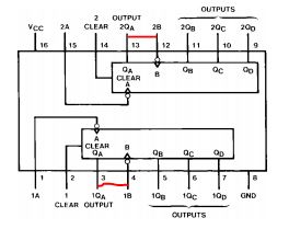
…A107 board with the LS390 installed.
With these fixes, the 100 kHz signal came back! And the gate LED flashing!!
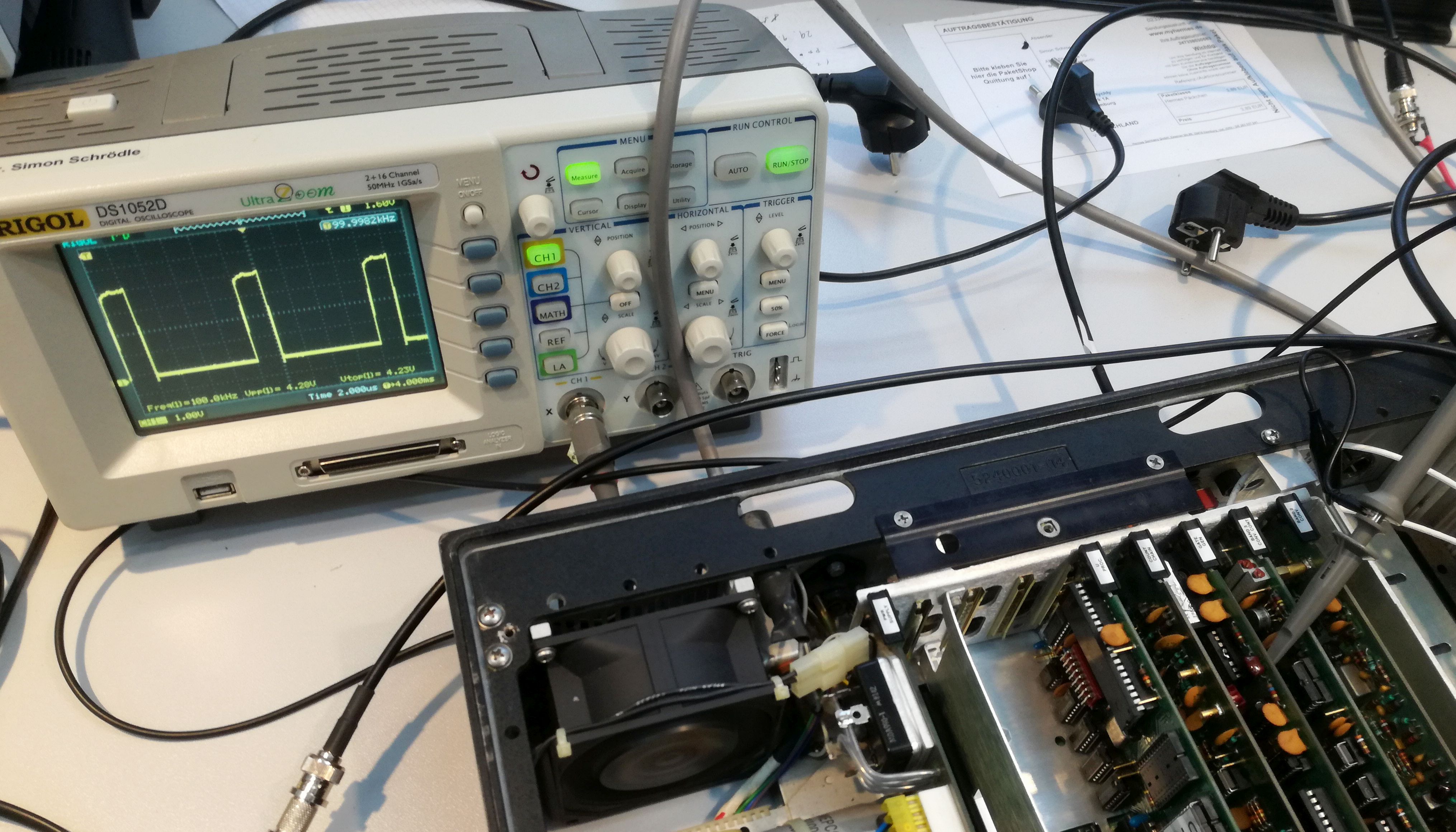
Tested with the test function 01 for some hours, and with some shaking and bending of the boards – just to be sure that the repair is permanent – all counting along fine. Also in band 3, no issues, and very good sensitivity all the way up to 18 GHz.
The last thing to do to before the unit will leave the workshop – adjusted the TCXO to the right frequency, it was only off by a few Hz, after many years of aging.