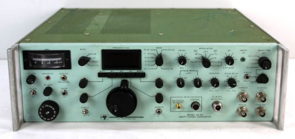
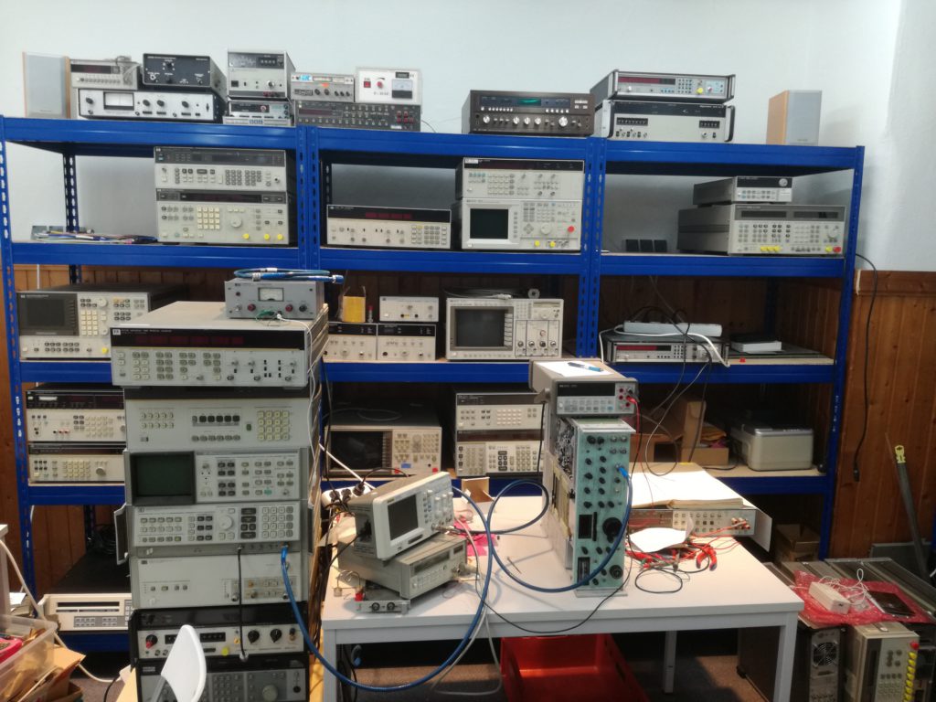
By luck and coincidence, I found another Micro-tel SG-811 generator on eBay, at a very reasonable price – sold as not working. Even non-working, these units are great because of the many microwave components contained: YIGs, filters, GHz-capable relais, SMA cables… and a lot of old-fashioned analog circuits.
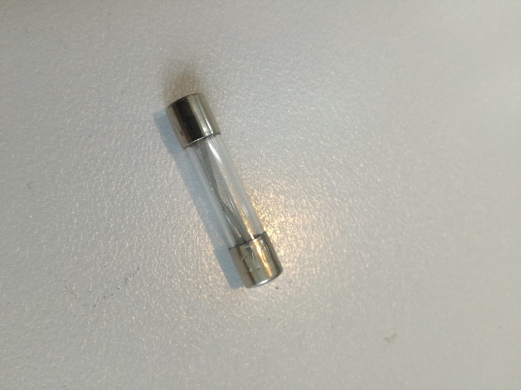
First check – the fuse! Someone recklessly put a 10 Amp fuse in, because the smaller fuses would blow. That’s never a good idea. Most probably we will have to deal with a power supply repair.
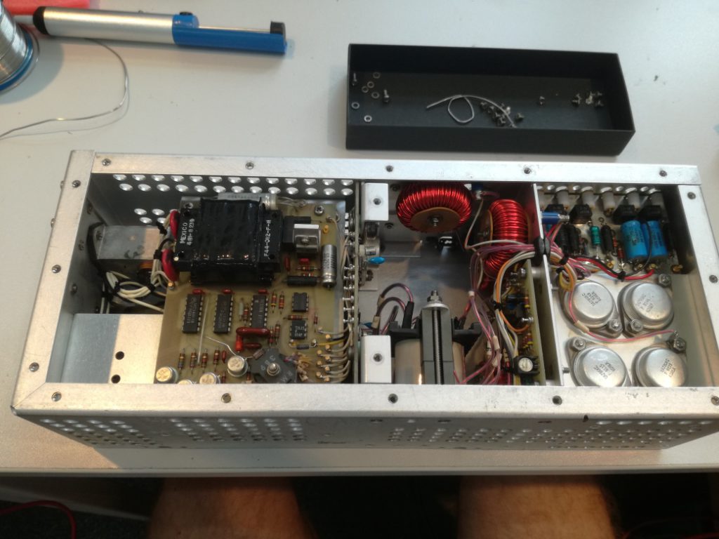
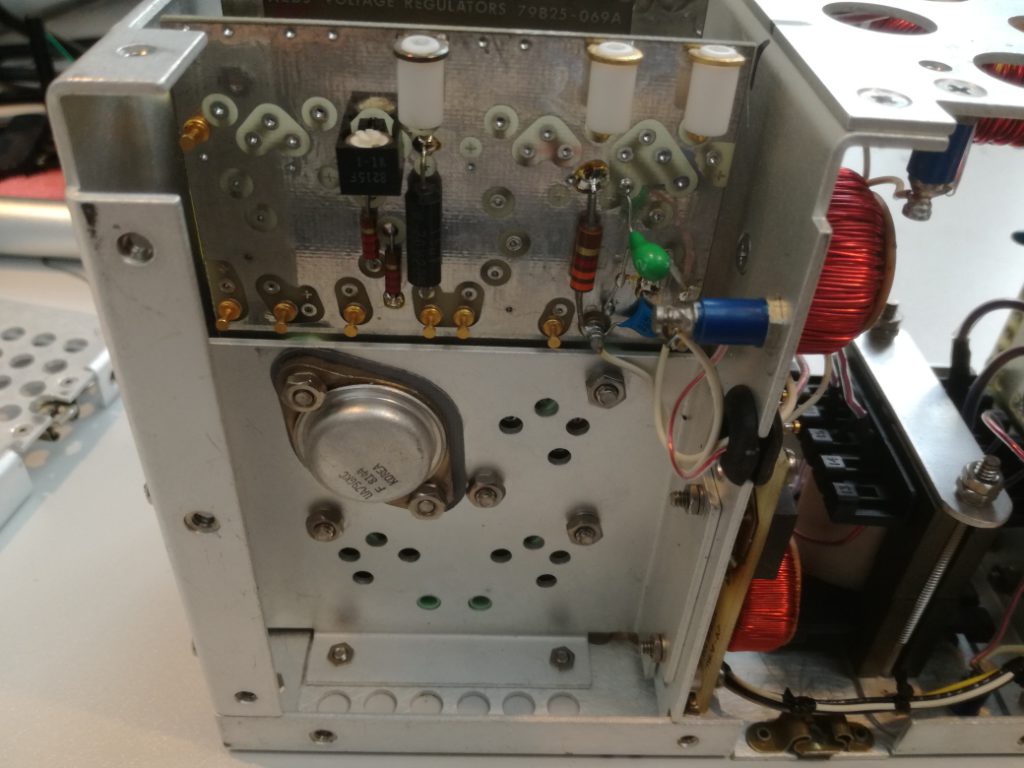
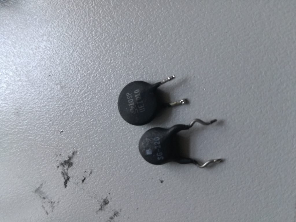
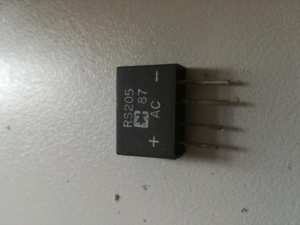
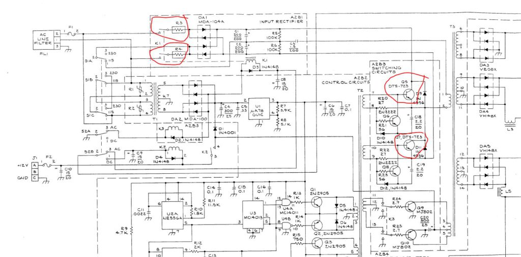
After detail assessment – the 24 V tantalum cap is shorted, maybe this triggered a sequence of faults: the main primary transistors (MJ12002), the rectifier, and two thermistors that limit the inrush current.
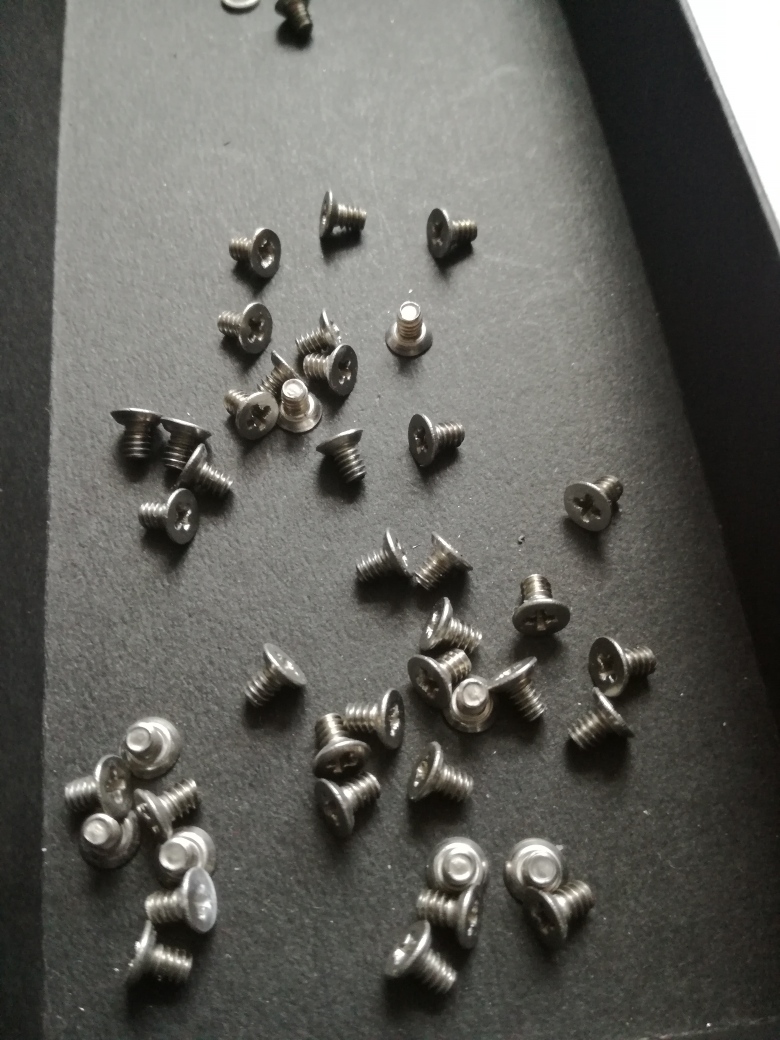
Micro-tel didnt safe on screws when they designed the power supply!!
These power thermistors are hard to get – I just desoldered two similar ones from old switchmode power supplies.
A dead rectifier – easily fixed.
All the parts labeled – also replaced the 2N2222 driver transistors, and two tantalum caps that were leaking current.
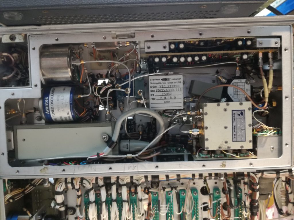
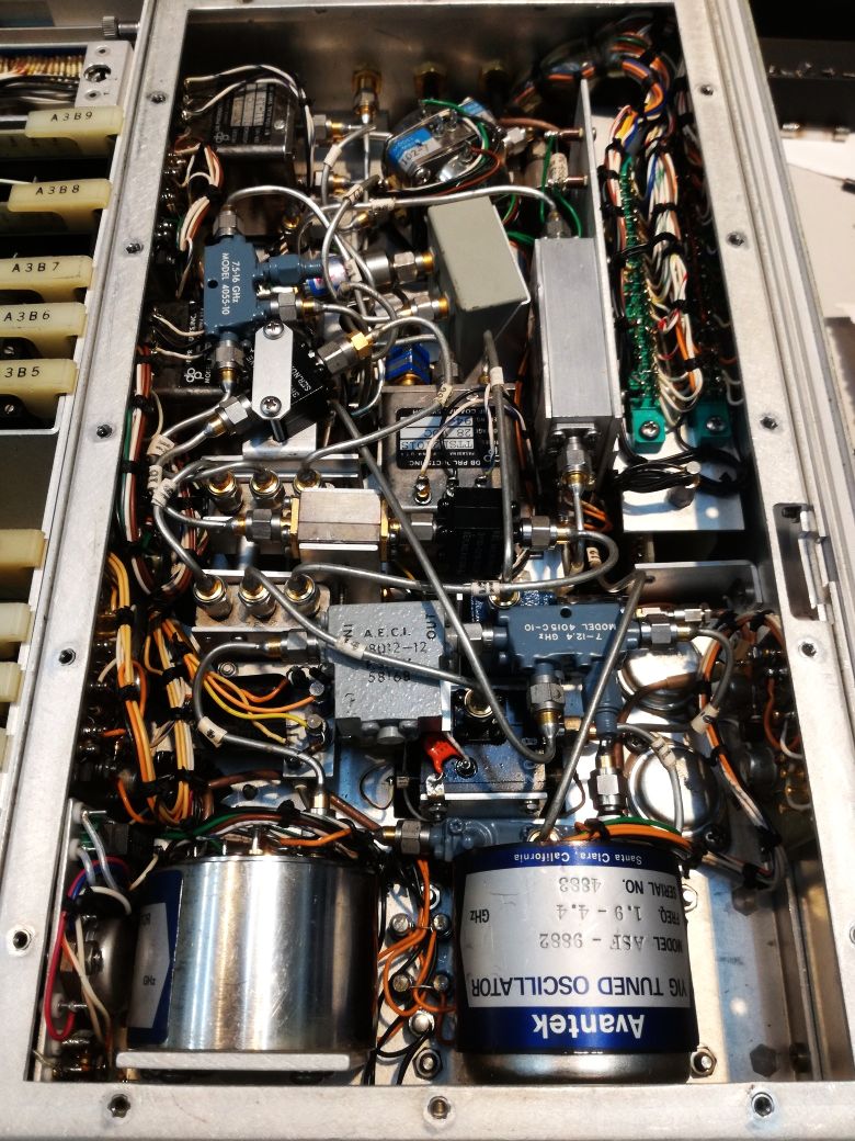
The most precious parts – the RF section.
A most complicated arrangement of oscillators, switches, couplers, and so on
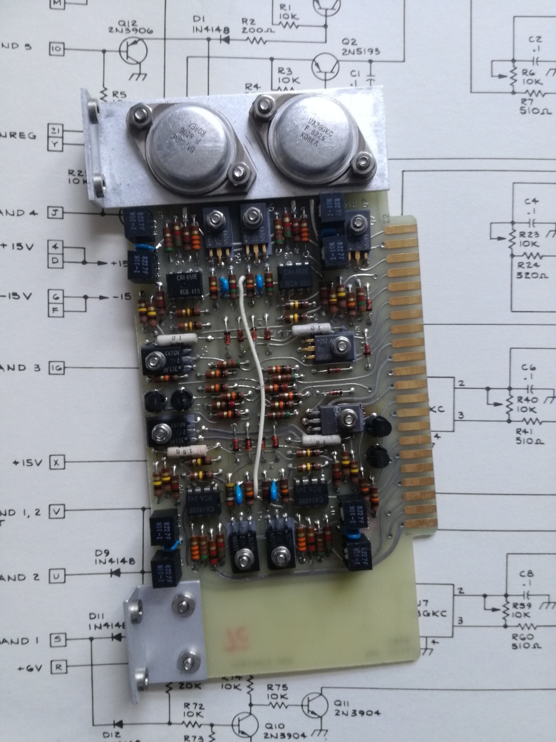
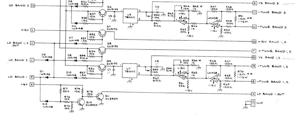
Some of the oscillators originally used in these units required a variable supply voltage to get stable power output, but strangely enough, the YIG oscillators fitted have built-in voltage regulators, and the supply voltage has no effect at all on their output. Still, the power supply board caused issues – end even overheated, because the voltage is set by very sensitive trimmers, and drifted above 18 Volt…
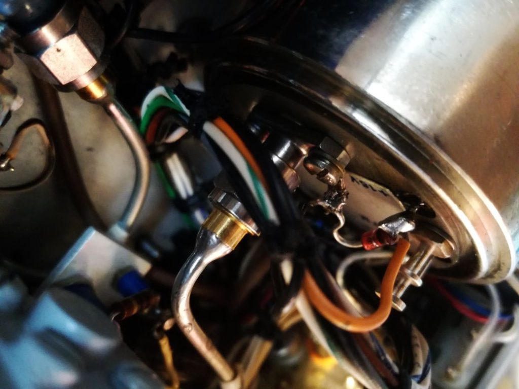
The YTO has a voltage protection diode – it was completely fried when I received the unit. Checked some good Advantek YTOs, these have 18 V 1.3 W Zeners for voltage protection.
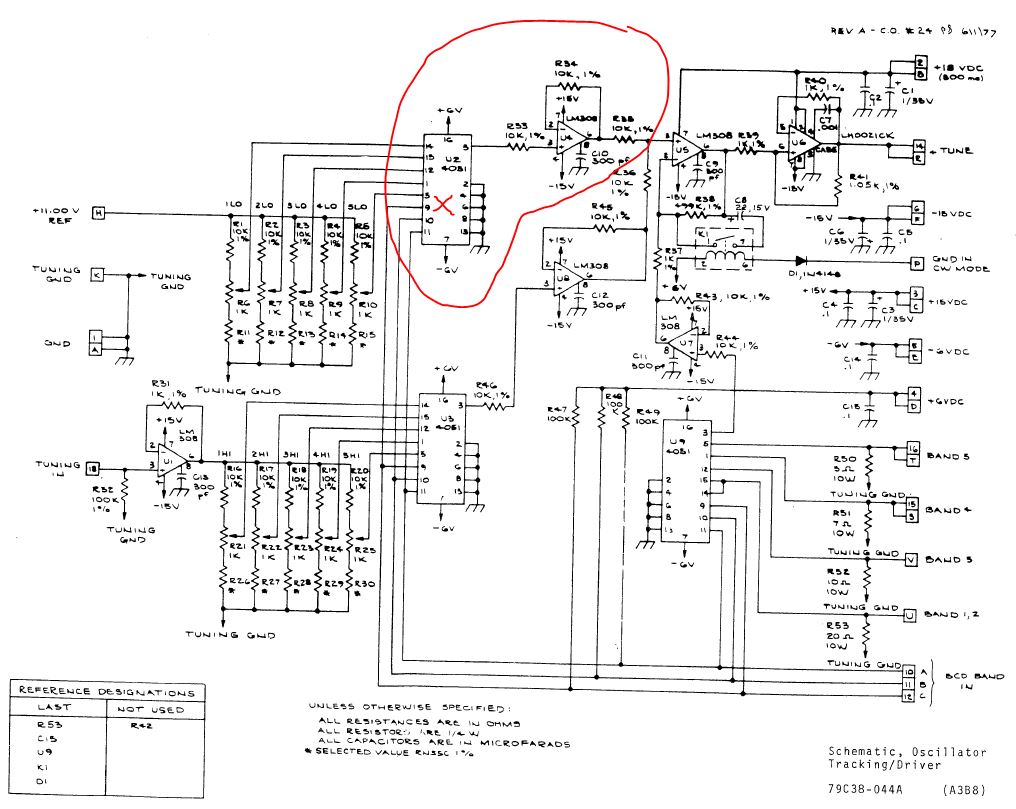
With power back on, and the voltage at the YTOs OK, still no good output – how can it be? Some issues with the oscillator driver board that sets the current of the main coil, and without a proper magnetic field, there won’t be any oscillation.
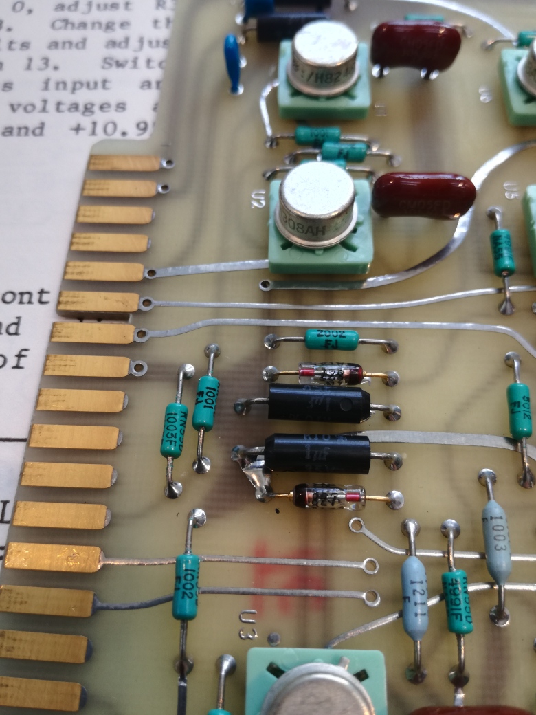
The precision resistors, seems they were hand soldered with some bad solder (traces of corrosion, and high melting point).
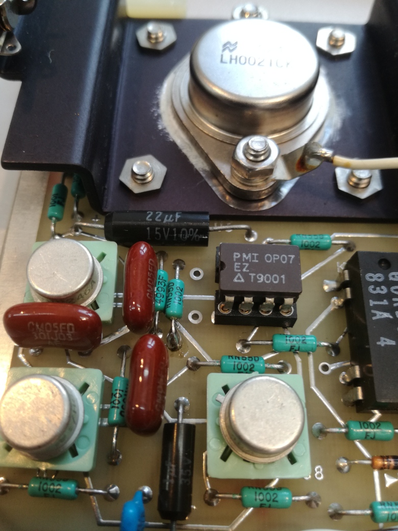
First, some trouble to find the dead part – thought it is one of the opamps, LM308, replaced it with a OP02. But no luck.
So I changed it back to the old LM308, just to keep all in original state.
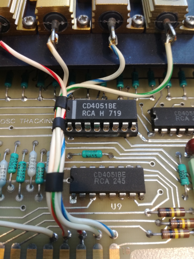
The bad guy… a 4051 multiplexer CMOS, these are notorious!
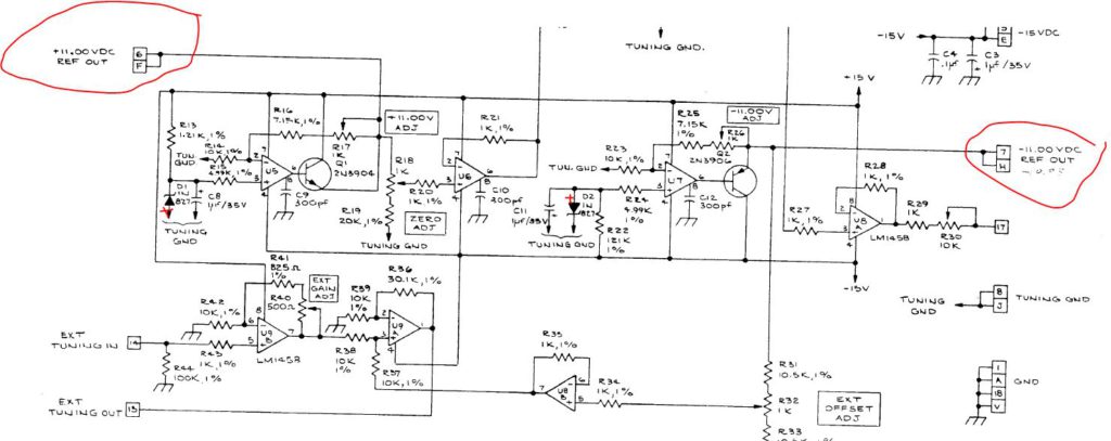
Another interesting assembly, the reference assy – the 1N 827 reference diodes where still very accurately set, only a few ppm of the 11.000 V, and -11.000 V!
After these repairs, and some adjustment, all is back to working condition!
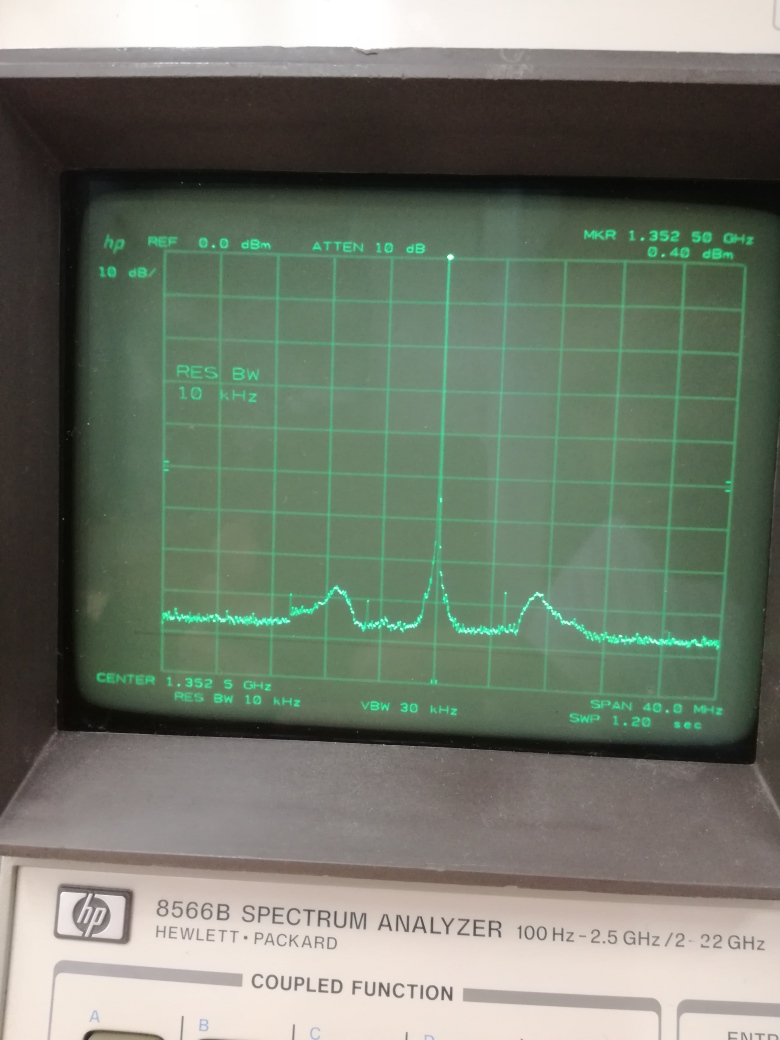
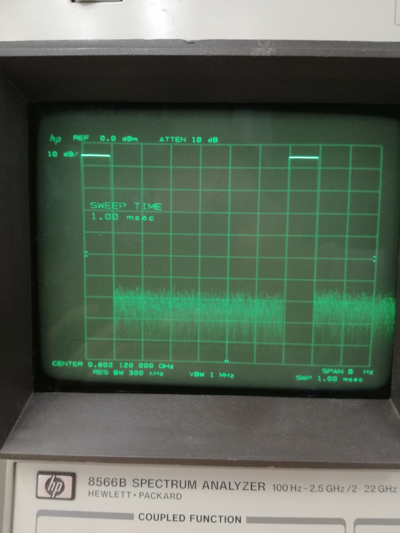
Checking out the signal on a 8566B analyzer. All good!
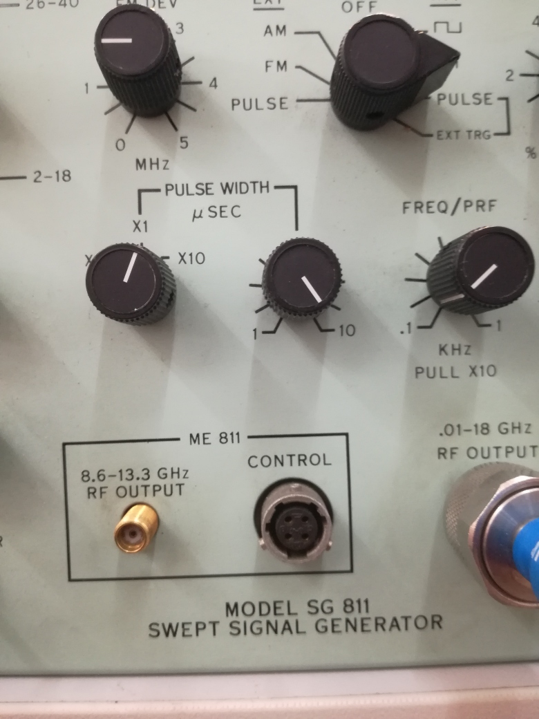
The pulse generator, also a great feature of this unit… 1 ms pulse.
down to 1 microsecond, no problem.
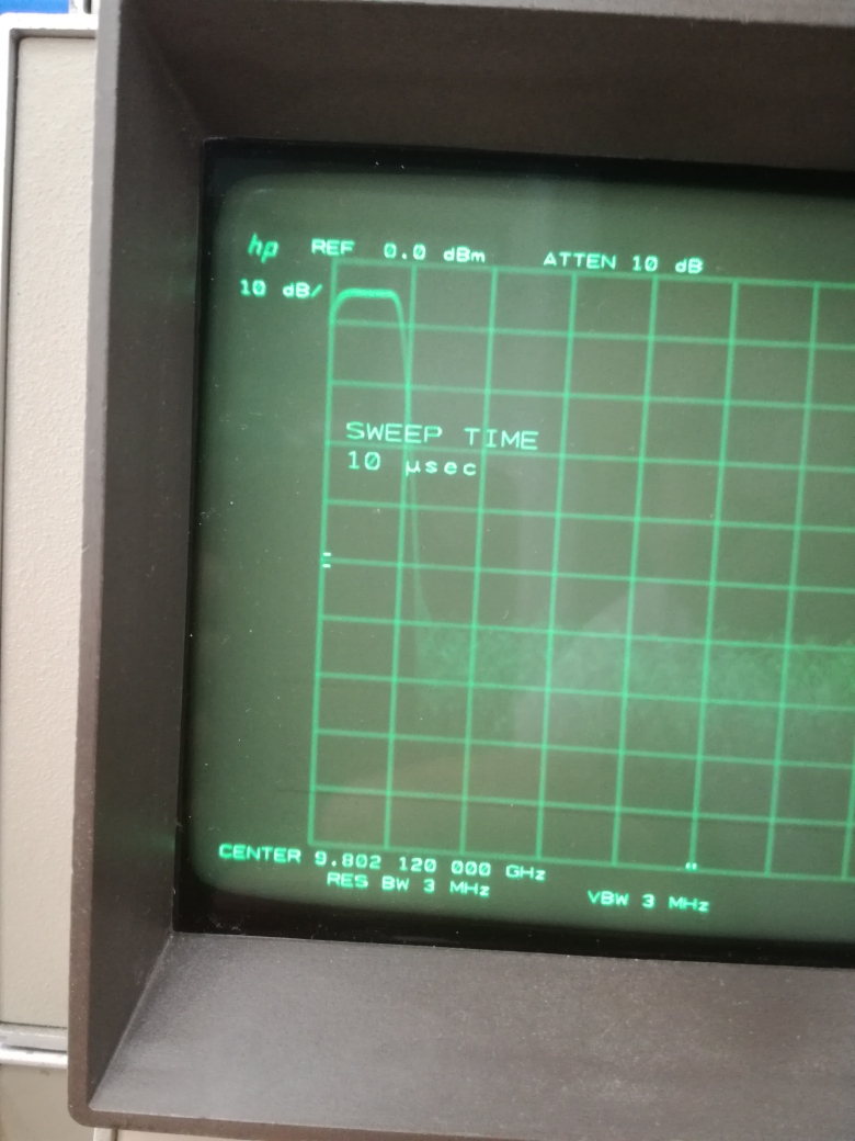
… 10 microsecond pulse…
The attenuator, a really high quality HP device.
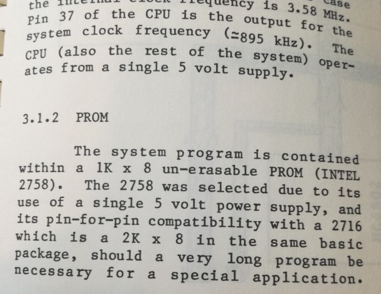
The manual has some remarkable comments – use a 2 kbyte memory, just in case a “really big program” would be needed in the future.
Still, I will do some alignment of the oscillators and filters… but that’s no big deal.

