
With the hardware already set up to provide a 10 MHz signal and electronic frequency correction, some optimization of the algorithm used for phase locking. It needs to be a really low frequency low pass filter (say, 0.001 Hz), and we need to deal with the discrete nature of the measurements and the quantization.
This is accomplished by three mathematical approaches
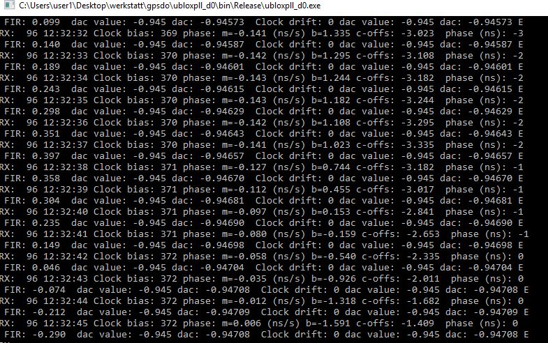
(1) The data is sent through a 32-parameter FIR low pass.
(2) The frequency drift is calculated for the last 32 seconds, and used as derivative signal, as long as the oscillator drift is less than 10e-9 (1 ns every second!).
The u-blox settings – these are no timing receivers, but I set the device for 2D stationary navigation, it gave the best results here. Also, better disable all messages you don’t need, it will be beneficial to avoid overloading of the slow serial interface (still running at 9600 baud).
Here some examples:
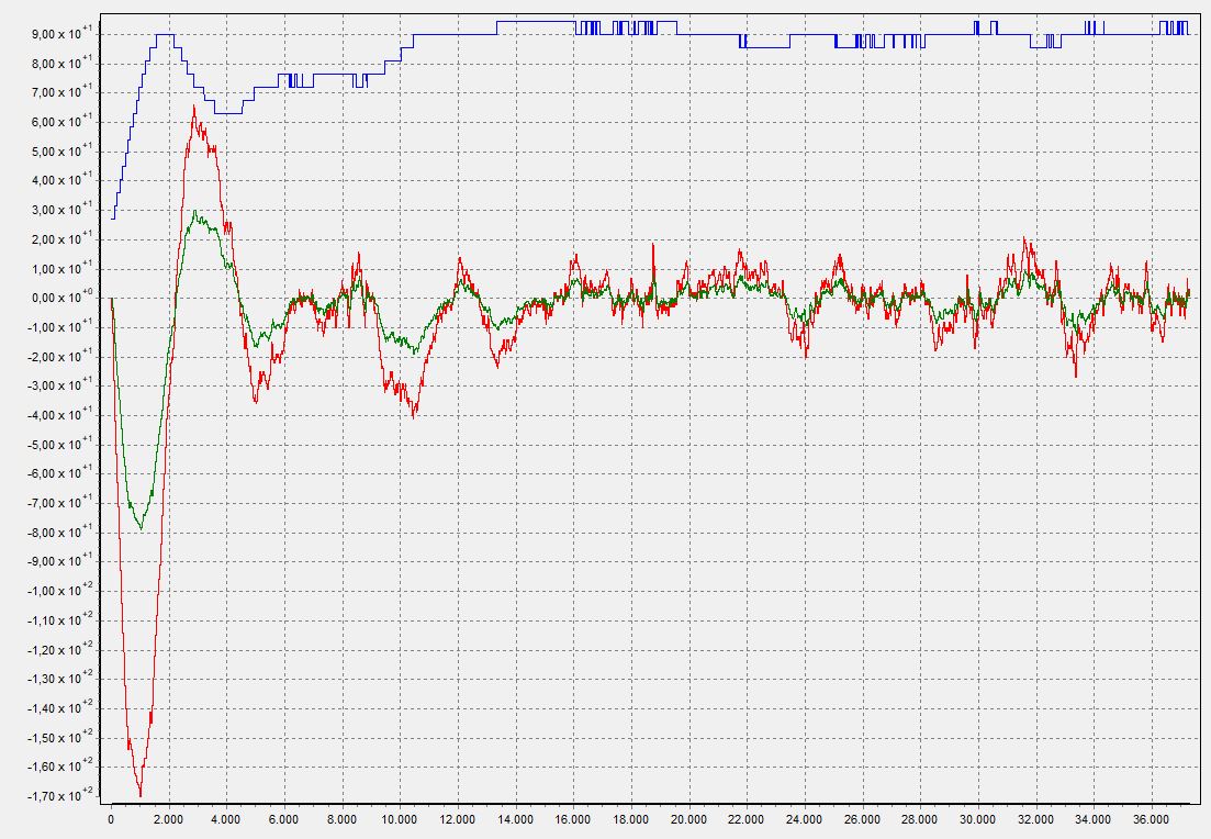
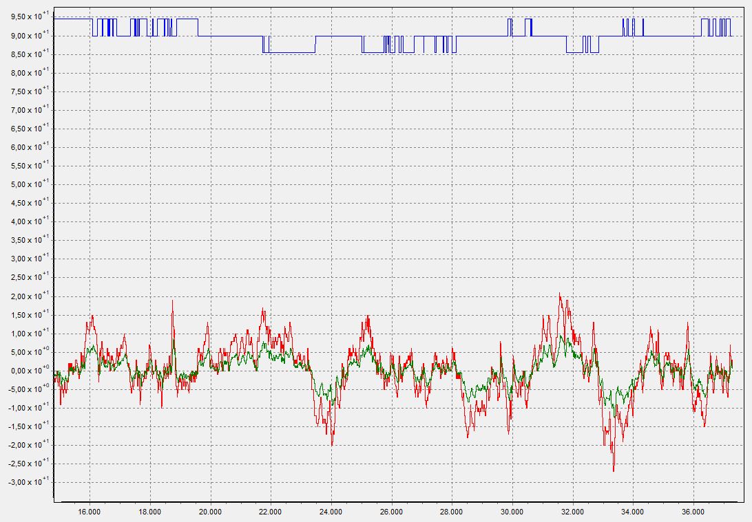
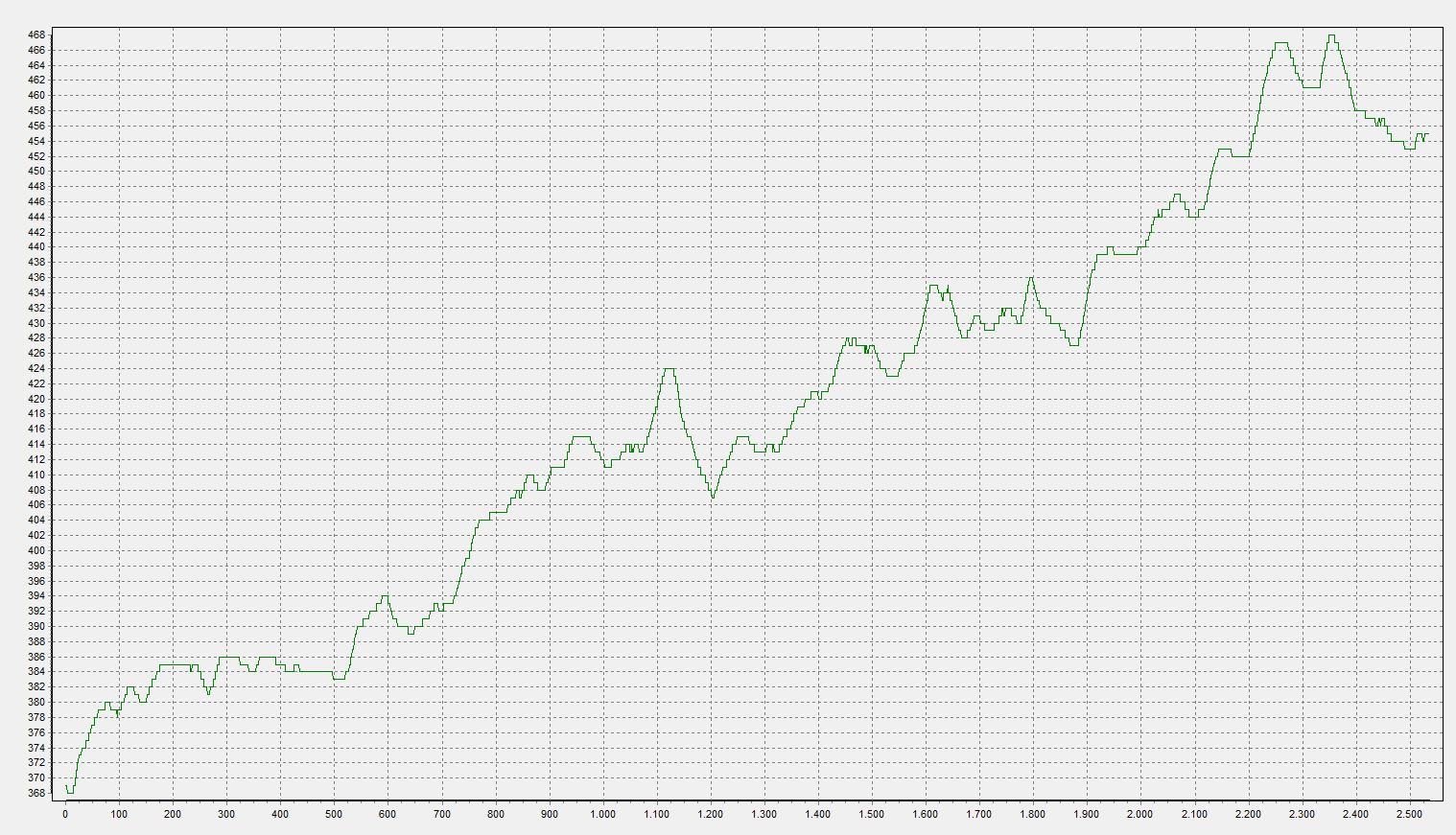
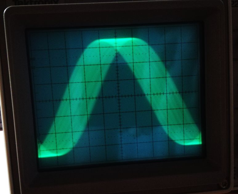
With the PLL open, the signal is drifting away, albeit, at a very small rate.
To check the stability and general behavior, I’m monitoring the 10 MHz signal on a scope, triggered by the time pulse (set to 100 kHz) of a 2nd u-blox receiver, sitting closeby. Horizontal deflection is 10 ns per div. Sure, the signal is broadened by the interpolation of the 2nd receiver, which has a free-running TCXO. Because of the synthesis of the 100 kHz signal from the internal 48 MHz, the trigger has about 20 ns jitter-no problem here, because the drift is much stronger and the phase of the 10 MHz signal relative to the 2nd receiver can easily be measured down to 1-2 ns.
Hello there! I just found your web site and it is a treasure of information! very interesting projects and expertise your have…
I am quite interested in your GPSDO project and experiments. Have you progressed on this subject since the last postings in 2018?
very interesting…
It progressed well and is working but I believe that a simple approach with a ocxo-PLL to clean up the 10 MHz (or, say 100 kHz) output of a u-blox will work equally well. I plan to post about it as soon as winter has arrived…
Thank You for replying! Yes, I have implemented a PLL fed from a Ublox M8M GPS – I tried with 100KHz and 1MHz reference from the M8M, and it works well, but it is more hardware, etc. The PLL loop control is also critical to ensure low phase noise, and still needs a lot of long time constant filtering on the control voltage to the OCXO. I am very interested to try your ‘NAX-Clock’ message control method to see what the difference may be between the two method types. Would you be prepared to share the software you used? Basically the software that uses the NAV_Clock message contents ( Clock Bias, error, etc) and the software for the filter that then generates the output control for the DAC…It would save a lot of time in learning from what you learnt! My OCXO is a 5MHz very good one from an old Hewlet Packard 5061A Cesium Beam standard – the Cesium tube is dead and so I am using all the ‘insides’ to make a GPS reference control – using the existing doubler/filter to get 10MHz, the existing dividers to get all the way down to 1Hz, etc. – A fun project!
Kind regards
Joe
V51JN
Sure, I am currently traveling but once back in the workshop I will send you what I have. The software is not very presentable but maybe you can reuse some parts.
Thank you Simon. That is kind of you. I need to give you my email? Or do you have it from this site? Not to sure how that works…
Kind Regards
Joe
I will use your gmail address that you entered along with the post. Otherwise you can reach me at simon@simonsdialogs.com
Thank You Simon – Email and info received – much appreciated!
Regards
Joe
Hello again Simon.
I have completed my GPSDO – I have sent you an email with some explanation and photos as I am not sure I can post photos here..
Thank you again for your Code assistance!
Regards
Joe