
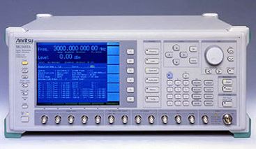
Along my search for used&broken&cheap test equipment in Japan I came across a Anritsu MG3681A 3 GHz generator, it has quite impressive specs, and the unit offered had the full CDMA-W digital package, allowing a whole lot of experiments with digital modulation. The price was right (just about EUR 100 plus shipping!), so this was soon to become the the first Anritsu gear in my workshop.
The information from the seller – at least it powers on, and frequency is locked. The unit also has the Option 02 OCXO, a really high quality 10 MHz source, so even if all the machine is defective and broken, there is still good use for it, just using the parts for other projects.

Further tests confirmed that the output is low, albeit, it is locked and even the ALC (level control) appears to be working.
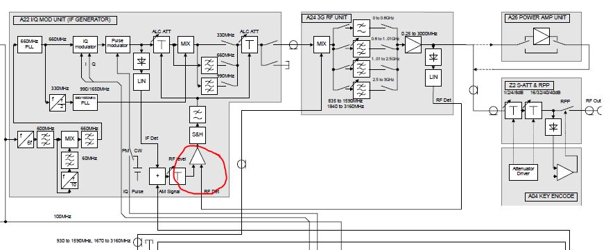
Without having a good insight into the workings of this unit, also because of lacking schematics and details, I decided to do some tests. After removing about 100 screws or more (the unit has double and tripple shielding to avoid RF leakage), I got access to the attenuator and signals going to the attenuator (see block diagram). Obviously, something is wrong with either the attenuator (a burned segment or reverse power protection element introducing loss?) or the detector, or the ALC circuit itself.
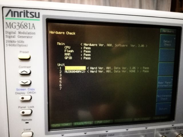
Checking the diagnostic messages – the MG3681A thinks all is good! The only strange thing is that I don’t get any ALC error message (unleveled message, even when dialing in +17 dBm output, which corresponds to about 12 dBm output at present).
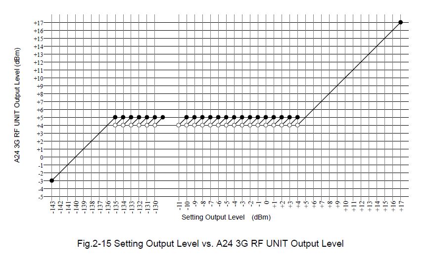
A through check of the attenuator shows that it is working in 1 dB steps – i.e., the MG3561A is only using a 1 dB for linear adjustment of power, and all the other attenuation is by the switched/mechanical attenuator. This true up to +5 dB, above 5 dB, the attenuator is set to 0 dB and the gain of the output amp is determining the power. Same below -135 dBm. Attached detail from the service manual shows the detail.
After all, I was able to confirm good working condition of the attenuator.
Next, some tests of the output level of the RF amp assy, which feeds the attenuator. And, not surprisingly, the output power is already low before entering the attenuator. All is leveled and working as it should, and also flat regulation with frequency (!), but too low power.
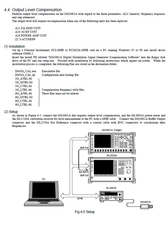
Following the service manual, there is a complicated procedure for output power adjustment. It requires some special software, and two more Advantek instruments that are hard to come buy, and actually, we don’t have any issue with flatness or response, but just an offset of the level. So we should be able to correct this somewhere in the analog circuit, say, in the opamp doing the ALC control, or in the DAC setting the output level.
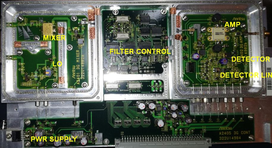
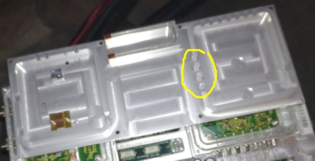
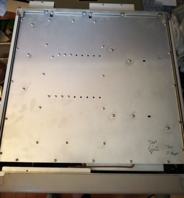
Studying the circuit a bit, with the block diagram, and some general knowledge about such analyzer. The function blocks are clear. And a quick test showed that the level detector itself is working. So we need to troubleshoot the level control loop and opamp. Another interesting observation – the digital control of the final amp is actually done by light beams (IR diode sending, IR receiver), to transmit digital information noise-free to the final amplifier. Note the gaps in the cover, marked in the yellow circle. That’s where the light passes from the digital control to the amplifier section.
This level control circuitry is part of the modulation assembly, which is a fairly complex assembly. But, what is this? There are several micro-size adjustment pots. Could it be that one of the relates to the ALC loop? How can we find out? Easy enough, we monitor the output with a power meter, and turn each of the pots a bit, of course, not without clearly noting its original position. The 3rd adjustment pot – it does affect the output power! And, surprisingly, I can easily increase the power by about 6 dB.

With this adjustment identified (I could not find any reference in the service manual to these adjustments), I rechecked and readjusted it output power at a range of frequencies from 1 MHz, 10 MHz up to 3 GHz, and flatness is in fact very good! Also, I get the expected performance now when increasing the output power past about +14 dBm – an uncal-unleveled message is coming up, indicating that the maximum output power has been reached (the MG3681A can provide about 14-15 dBm leveled power over the full range).
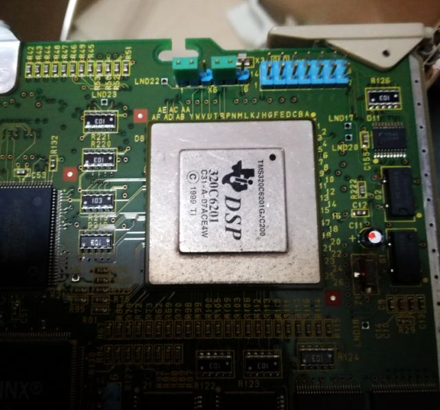
A good amount of logic in programmable devices (firmware of MG3681A can be updated, if you have any such firmware, please share with we!).

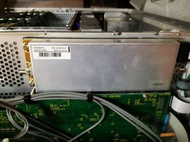
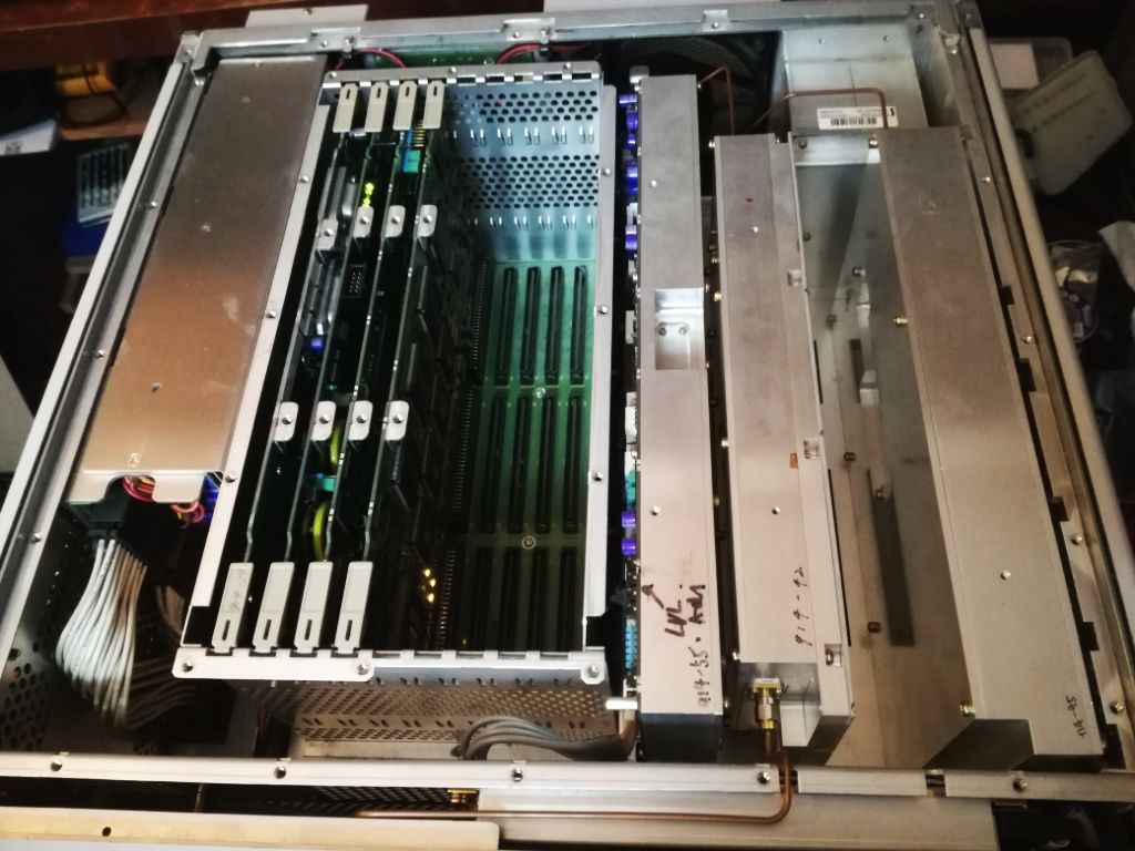
Another view of the inside of the instrument – it is what I call the Japanese test equipment design, a lot of empty space, all well arranged, and many different types of assemblies and hardware with great attention to detail and sophistication, and some manual corrections with superfine wire. Because of such design, it also needs two fans – one for the power supply, and one for the main unit.
The CDMA-W functionality. Fully working at least as much as I can tell from spectral analysis of the digitally modulated signal.

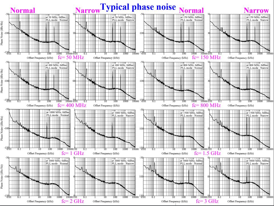
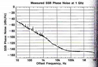
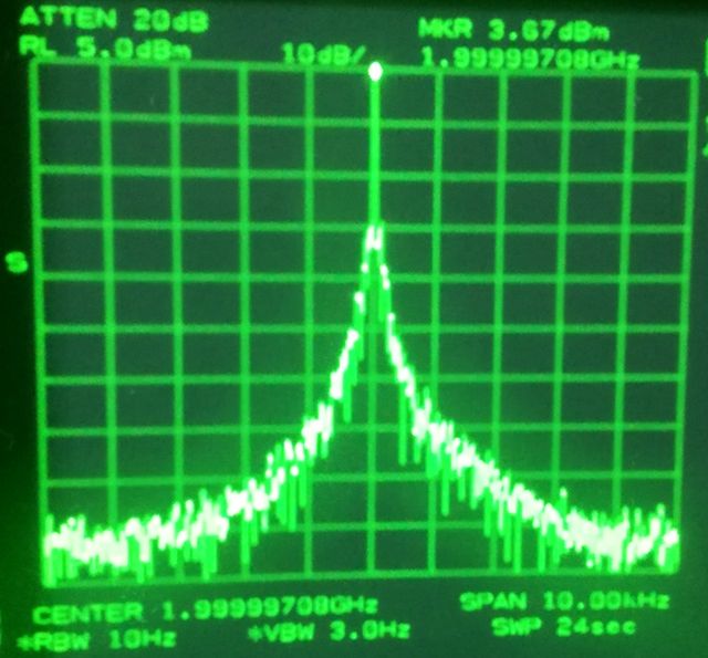
Some study of the phase noise performance. The MG3681 is not too bad, it has fairly low SSB noise, even close to the carrier.
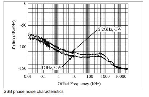
For comparison, the phase noise of a 8642B, which is a good HP generator, not the best for close in phase noise, but it is a low noise and heavy and sophisticated machine, even without any digital modulation.
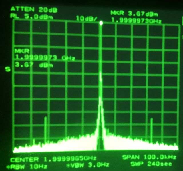
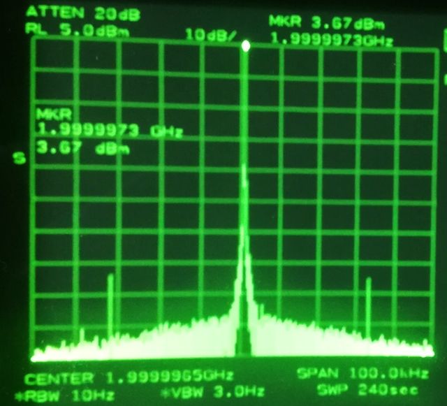
No sophisticated phase noise test gear set up here, but let’s study it on a 8561B analyzer, at 2 GHz frequency. At 100 kHz span, the noise of the analyzer dominates, and both the 8642B and MG3681A show very much the same levels.
MG3681A:
HP8642B:
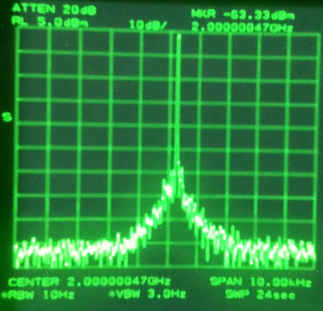
Close in, at 10 kHz, the MG3681A appears superior, maybe, by about 10 dB. Not bad!
MG3681A:
HP8642B:
With all the functions established again – some clean up: removed all the dust, checked all the connectors, and put the thing back together.
Now, all is hidden again under several sheets of metals, and all the many screws (not only many pieces, but also many kinds) back in. Let’s hope we don’t need to open it soon again!
Some useful documents:
Anritsu MG3681A Technical Description
Hello Simon,
Tnx for the manuals. I have a defect 3681a. Screen problem en will not start up after reset. It has also the RDP problem.
I got it from a fellow HAM for parts. I hope i can repair it.
Status now is no screen, i think no program?? and the RDP problem.
Hi Maarten,
I have a parts unit in case you need some specific part, if some parts have their number missing or burned off.
Simon
Hello Simon,
Tnx for your reply.
For now i don’t need any parts. It’s a winterproject and possibly have to move the shack to the attick!
Do you know if any person has the software.
Do you know if a testing menu, servicemode, is provided??
Grt, 73 Maarten
Hi, if you know how to do it, there is a memory stick and I could try to export the firmware. I have the cdma option software that loads from the stick. Anritsu also has firmware but I had no luck to get it from them after a few emails no reply (not the first time I find their service nonresponsive so I usually dont buy their equipment). There are no service functions, nothing significant.