
Finally, some spare parts arrived and now I can proceed with the repair of the HP 4192A power supply and power distribution cables.
First, the floating power supply. The main defect has been fixed, and I have been waiting for new-old-stock (NOS) 2n3725 transistors from a very reasonable Taiwanese dealer. These 4 parts arrived. All different case and vintages. Note that one of the transistors has a black pencil mark.
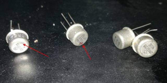
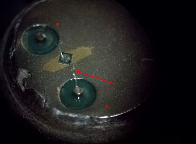
These parts didn’t look all too trustworthy – at least they are no fakes. So I went ahead and tested each transitor. One found defective, no signal on its base. Why is that? So I took a look inside, and indeed, the base bonding wire is blown. Judging from the ends of the bonding wire, it blew because of overcurrent. This is the part that had the pencil mark – maybe the former owner had already marked it as “defective”, and somehow the transistor made it to the trader.
Anyway, we only need two transistors to fix the assembly. And keep one as a spare. A quick test shows – no issues with the floating power supply, all stable and these transistors are not running hot.
![]()
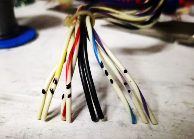
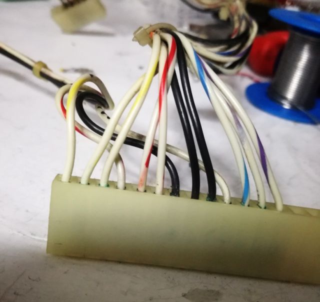
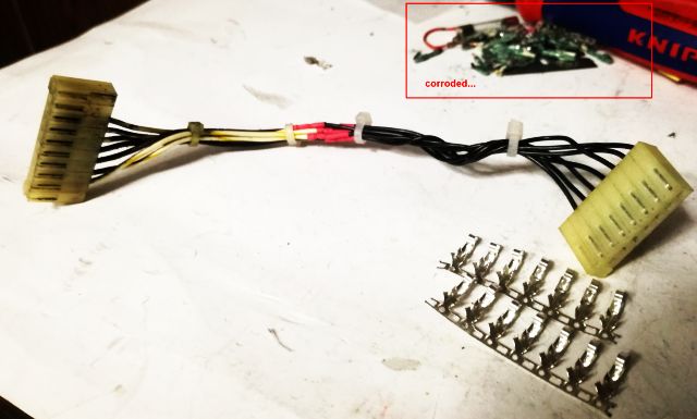
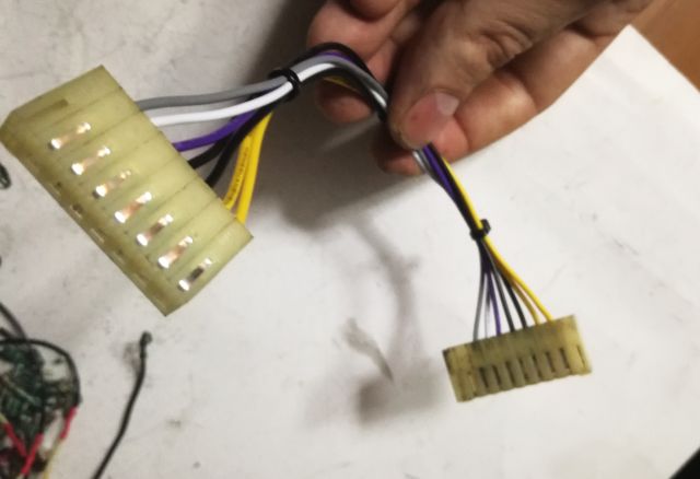
Next step, fixing the wires affected by the leaking electrolyte, especially, the Molex contact – they are all brittle, and have a green corroded layer on the surface.
Cutting the wires, there is even some slight corrosion inside, soaking up into the wire. Therefore I decided to solder the contacts, rather than just crimping the contact. This way, I can see if the solder is flowing, which will ensure a good contact.
Seems like a huge task to rewire all these connectors, but if you have a steady hand and some patience, it won’t take more than 1 hour.
Make sure not to mix any wired – it may destruct the 4192A beyond reasonable repair. So I took picutures, and notes, and marked the wires additionally.
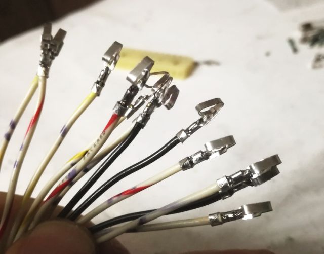
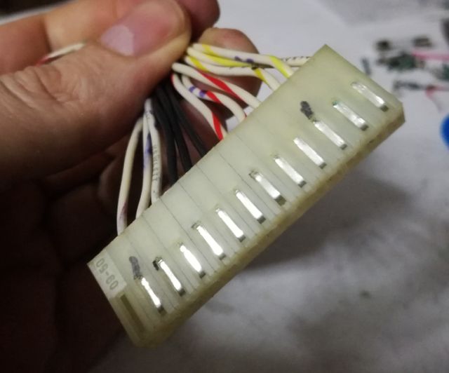
The rewired connector – all shiny contacts!
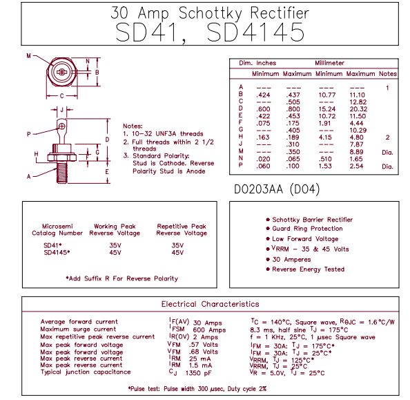
Further on to the next issue. The rectifier diodes of the 5 V digital supply. My original plan was to install a Schottky double diode.
While one of the original diodes was non-working, the other one looked good, at least electrically. Upon disassembly, it turned out to be quite bad as well:
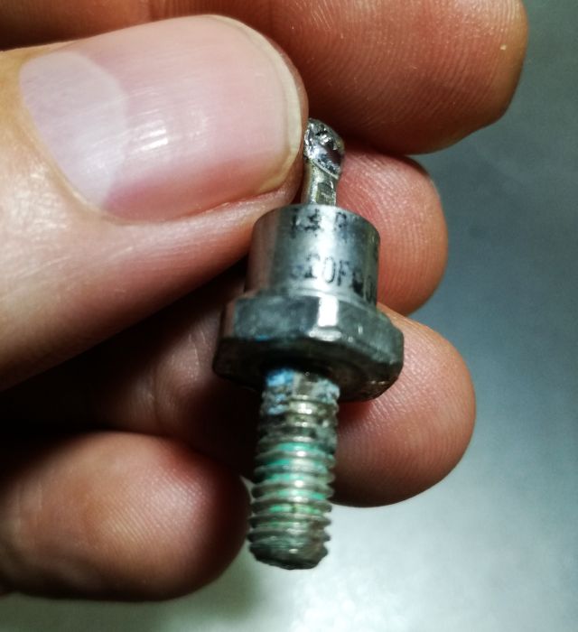
Then, I remembered a pair of SD 41 diodes at the bottom of my spare part pile (a board from a HP 8662A power supply), so I dediced to go forward with a 1:1 repair – fitting diodes of the same case rather than a modern part (and, I found good SD 41 diodes in Germany at low cost, so I have ordered a few as spare parts).
The typical current needed for the HP 4192A – about 2-2.5 Amp for the 5 V digital supply rail. With the unique nature of the 4192A CPU board, I didn’t want to risk anything, so I put the supply to a good test with an electronic load. And it easily can provide 2 Amps, at the right voltage.
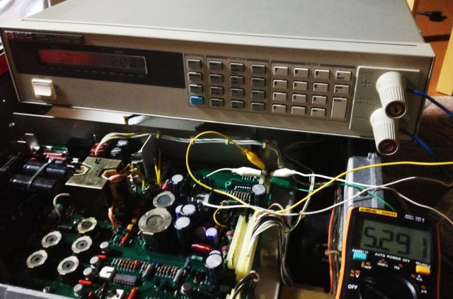
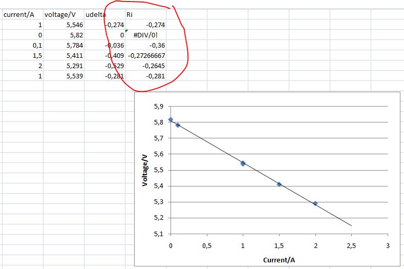
The digital supply has no regulation, the output voltage will depend on the load. But how strong is this dependence – any risk to drop out of the 4.75-5.25 range that is prefered by most TTL logic?
An easy thing to establish with the electronic load – see diagram below. Internal resistance is about 0.27 Ohms, it is quite stable, slightly at the high end of the range.
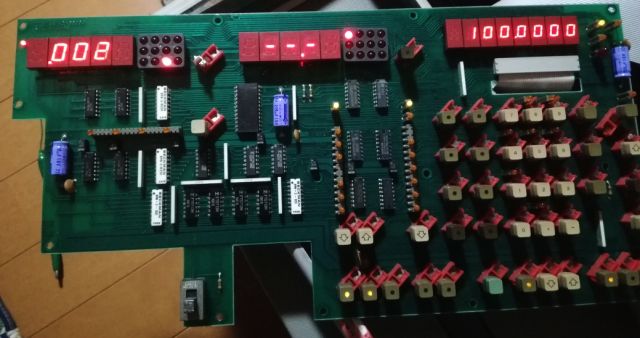
After all these repairs – let’s put it to a test. Still, all is in pieces, but, the 4192A is running through the startup tests with no problem and showing activity! So it seems the EPROMS are good, and chances are, we can get it back to work.
Celebrated a bit too early – some issues when moving the board-touching the cables to the CPU board. Probably, contact issues with the corroded wires.
The digital supply connector was very close to the leaking batteries, so the wires and connectors were damaged so much that I first had to cut about 8 cm of wire, to get to some copper that would accept solder. Not good, but I thought it would work for a temporary repair, which it did. But it also caused the unrealiable operation, because the corrosion extended all the way to the CPU connector.
Easy fix – just rewired the whole thing, again, taking extra care not to mix any wires or causing any shorts. Wire is AWG22, UL 1007 PVC insulated. All the contact were crimped and soldered to make sure there is good, realiable contact.
With this “new” cable, no sensitivity to touch any more, the CPU board is now getting stable power.