HP 11517A aka 08747-60022 Harmonic Mixer: a little study of a very intriguing device

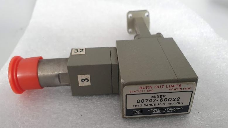
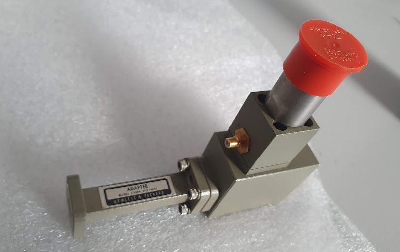
As part of a HP R8747A 26.5-40 GHz reflection/transmission test unit (for the 8411A network analyzer; 6300 USD in 1973 — about 40 kEUR today), I got two HP 08747-60022 harmonic mixers, one didn’t seem to work right, the diode has just 0.2 V voltage drop. These were fairly fragile devices, only designed for 1 mW of power, and very static sensitive, point contact devices.
In addition to the regular 11517A, the 08747-60022 has a bias connection (needs about 1.5 V DC bias, center positive).

The main unit can work from 12 to about 40 GHz, with a set of adaptor waveguides.

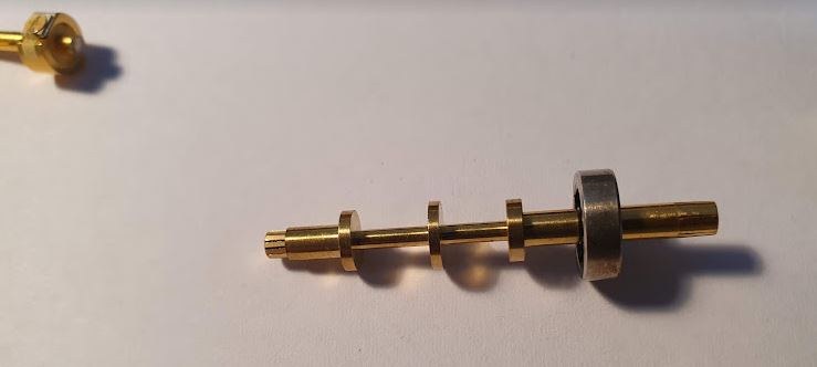
The unit can be taken apart, all precision machined.

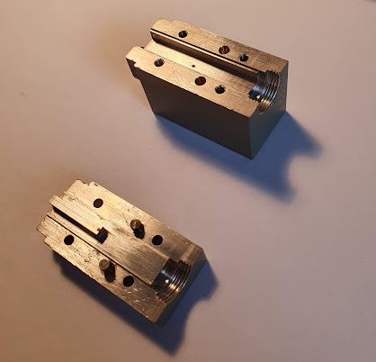
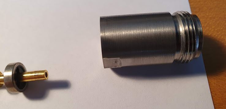
The diode is pressed in, on some holder (haven’t tried to remove it from the case).

There are several other precision parts, a coaxial resistor, held on to the diode with a spring.

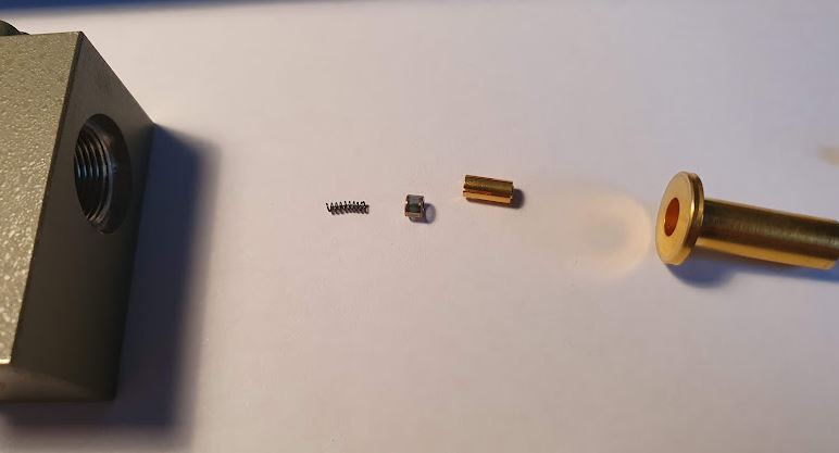
There is also a spacer, with a very flat capacitor, a DC block. The spacer is modified to connect the center conductor to a surface at the perimeter (used for DC bias).

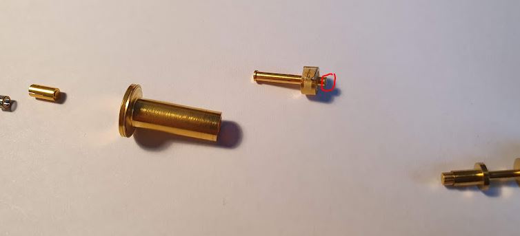
Further up, there is a low-pass, machined from a single piece and gold plated.

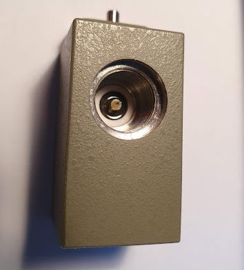
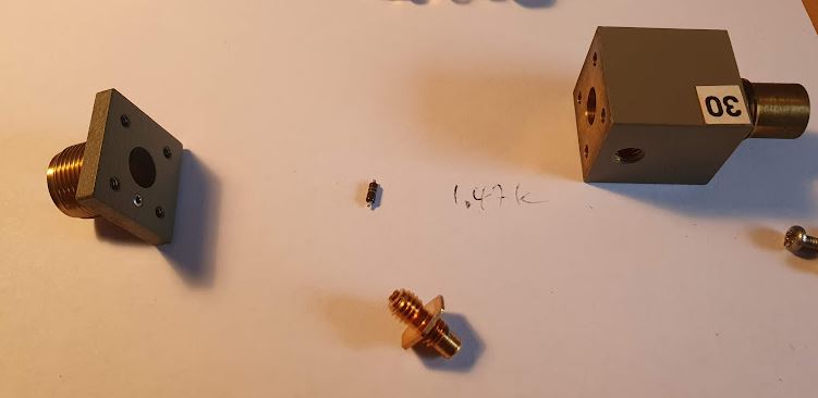
The N-type connector, stainless, is screwed on.

The DC bias uses a small 1.5 kOhms resistor, and a custom connector, so that the resistor is pushed onto the spacers’s connection.

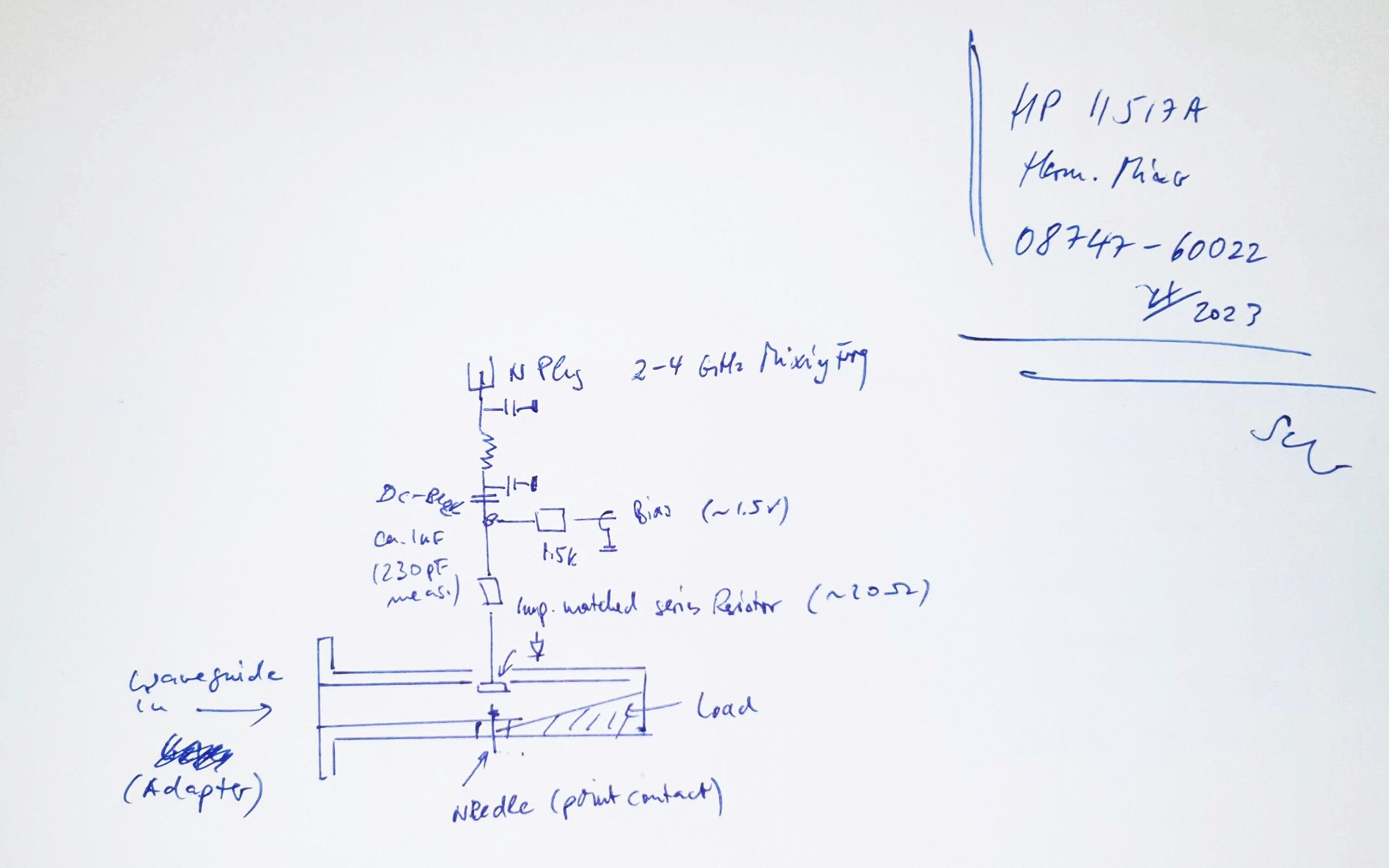
Here, a quick schematic. Seems a lot of engineering went into this device…

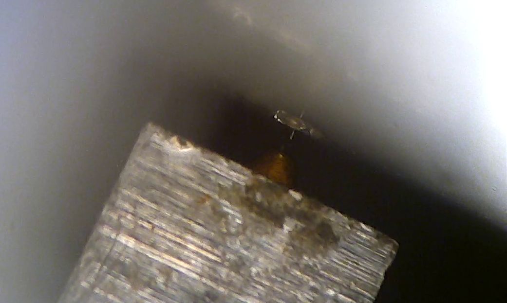
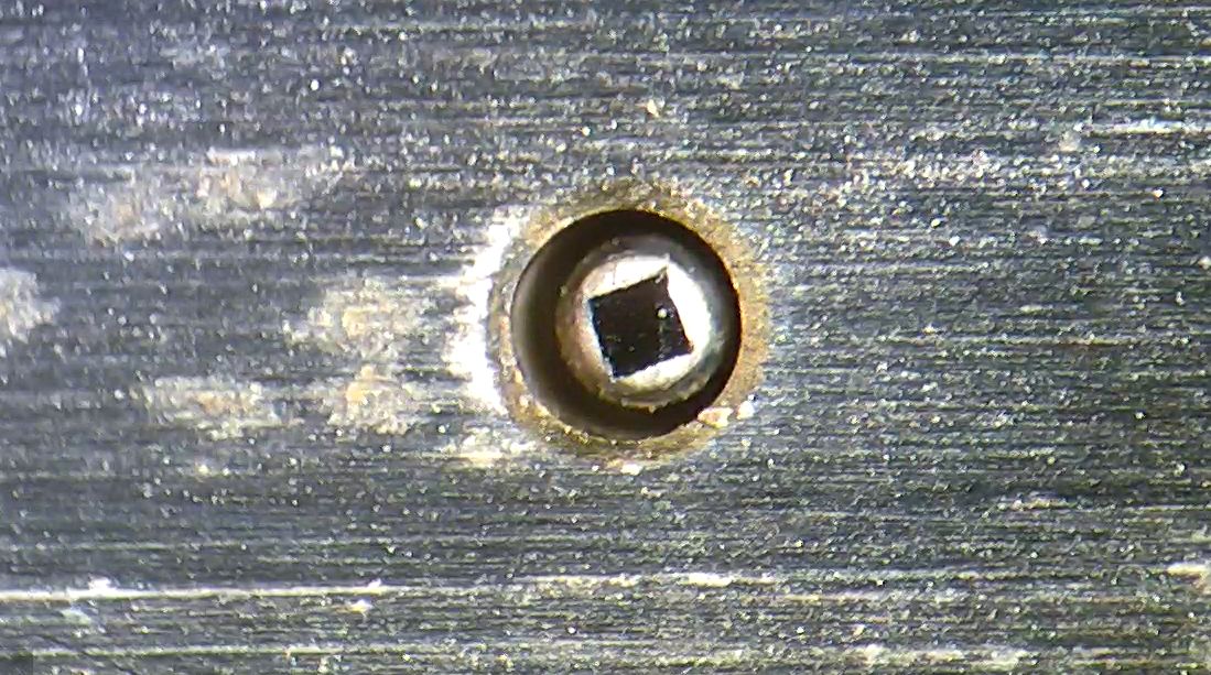
Finally, we need a microscope to study further here, the diode (the square), about 0.25 mm side length. It is isolated from the case by an air gap.

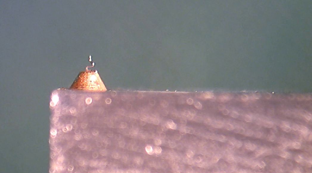
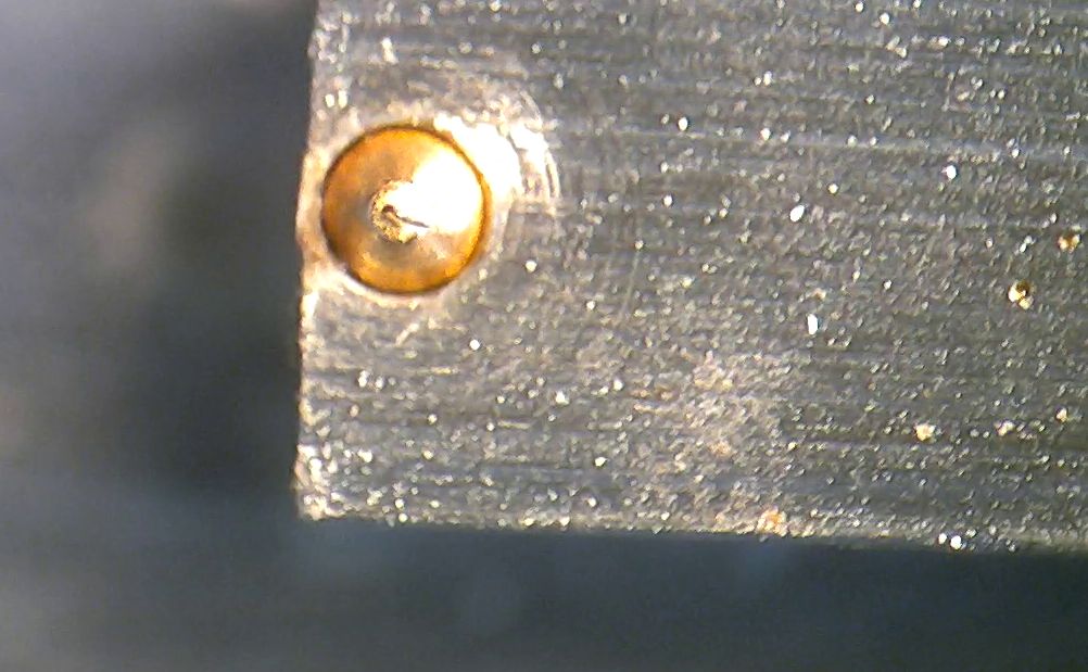
The diode is made by a contact junction, a small tungsten(?) whisker.

Probably, this whisker needed some adjustment during manufacturing. I tried to adjust it a bit, but this didn’t change the diode characteristics of my broken unit, unfortunately (anyway, these devices are more for study than for use; currently using only cartridge-based diode mixers).

Also, looking into the waveguide of the assembled mixer, with good long-range optics, I could get a shot of the actual point contact in action. Very interesting historic technology.

Spring repairs: Fixing and frost-proofing ball valve

Recently, I have been setting up the watering system for my vegetable garden again. In my area, the soil is a little sandy, not bad for growing vegetables because slugs and snails don’t like such soil, but surely it needs proper watering.
All in all it is about 200 meters of 16 mm drip irrigation pipe, 16 mm size, with drippers every ~33 cm, nominal 2.1 L/h each. The system is run at about 1.5 bar. Some specific plants like pumpkins and certain berry shrubs in other area of the garden have their own supply by 4 mm tubing and individual adjustable drippers.

In the past years, the system has severed me well, and just last year, I have upgraded the water supply by setting up a new well. So there is plenty of water, and every day, at least in summer, the system supplies about 400 L a day, in two portions (like, at 6:30 am and 6:30 pm). Glad I don’t have to carry all that water.

All the water system, pump and distribution piping had been empty over winter, to avoid frost damage to the pipes. I keep the ball valves at about 45° angle, but this year this didn’t help to prevent damage to one of the valves (all the other valves are OK).

It is a combined, low cost China-made ball valve with strainer, I bought two of these some years back.

It is tight when closed, but when opened, water comes out at the crack indicated in the picture.

How can this have frost damage? Well, with the pipe empty, it should be safe? There is considerable dead space in this valve, the ball also has an indentation (cut-out) at the side opposite to the handle. It is brass, chromium plated.

As luck would have it, I had the second valve still in a box, it had been in service for some years until someone broke-off the handle (never throw away parts that may be suitable as spare part donor…). Surely it would be quick to just replace it, potentially, even with a better quality ball valve, etc., but why now study it and fix it?

Breaking open the valve, the two parts are screwed together fairly hard, and glued with some kind of epoxy or similar glue.

But nothing that can withstand a large spanner and a pipe wrench! So, the front part with the PTFE seal looks good. Also the spare valve (with the handle missing/broken off) was disassembled in no time.

Now, how to frost-proof ball valves? It is quite easy, and a well-known trick. Just dill a hole, about 3-4 mm in the far side (low pressure side) of the ball, then it will drain the dead space, when left open (or at an angle).

It is essential to remove any burrs, so I countersunk the hole, and polished the edge with some find sandpaper.

Everything put back together, I used some acrylic compound to seal and tighten the screw threads of the two-part valve. Good as new!