HPAK (HP Agilent Keysight) 8904A Multifunction Synthesizer

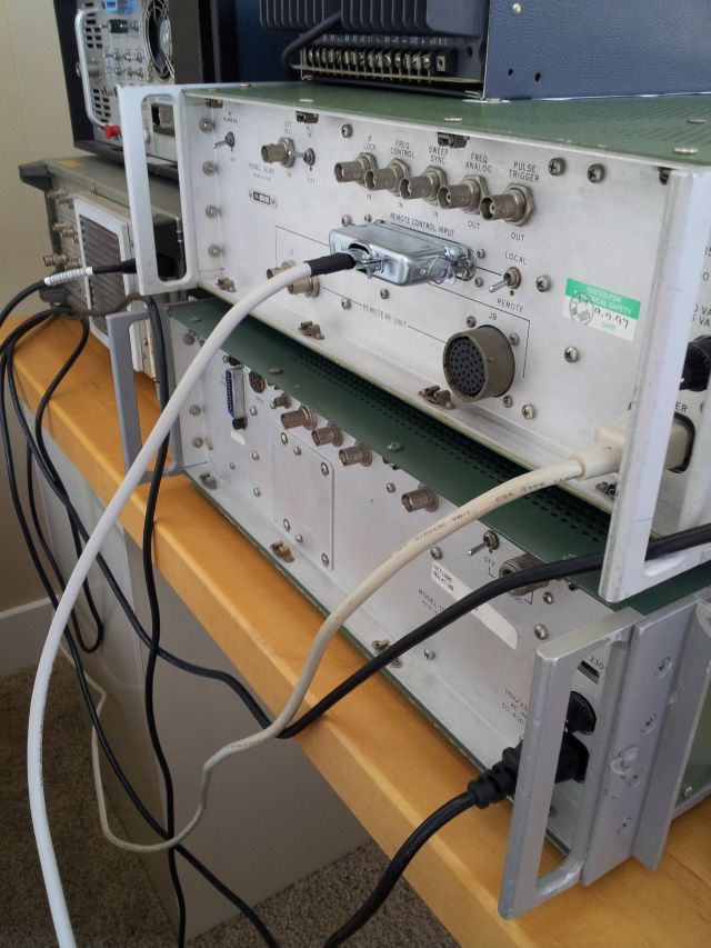
The HPAK 8904A – you will find the detailled specs elsewhere on the web, it is a one-of-its-kind instrument, an early type of arbitrary waveform generator, capable of frequencies up to 600 kHz, but its mainstay is the audio region.
Why is it so unique, well, it has a complex (some say, difficult to use, but are there any easier ways?) user interface that let’s you program all kinds of test signals without any time lost for generating complex waveform bit by bit, uploading it to a modern arbitrary generator, and so on. The HPAK 8904A support all the common modulation features, AM, FM, Phase, and additionally, DSBSC (double sideband supressed carrier) and Pulse modulation. It can gernerate FM stereo test signals, various other types of composite signals, DTMF tones, just to name a few. In fact, HPAK has published a catalog, with some of the common waveform (will try some of them later).

Most importantly, your plain 8904A might not be able to do all these things, because all the nice and special functionality is only available with option 001, which is, believe it or not, a software option (to my best knowledge, one of the earliest occurrences of a really powerful software option feature for HPAK equipment).

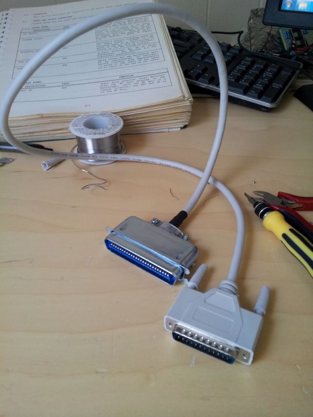
The unit I’m using came with option 002, two channels, but not with option 001 – well, it’s software only, all you need is a serial and key, and some intructions – which I will be happy to provide to you, when needed.

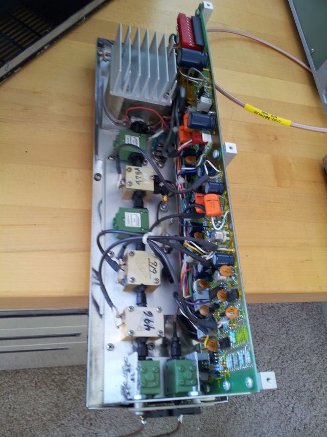
But before we start: the unit discussed here came from an undisclosed source, and failed power on test (no noise or other signs of functionality). Once opened up, big surprise, HPAK was using a Computer Products switchmode supply, 90 Watts, Model XL51-5601. Fair enough, this is a quality supply, but somethings must have gone wrong – no power.

20140827_075955

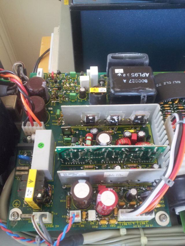
Troubleshooting a switchmode supply, with my somewhat limited workshop here in the US – well, it’s worth a try. No schematic, so hoping that it failed because of one of the more obvious defect modes. And, fair enough, here are the cuprits: FES8DT Schottky diodes, the secondary rectifiers – 2 of 3 were dead.

20140827_084909

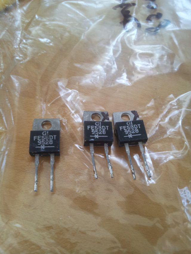
The FES8DT are 200 V, 8 A, 85 pF, 0.95 V drop devices. 35 ns recovery time. 125 A surge current. Seems they don’t fully hold up to the requirements.

Remotely controlling the Micro-Tel SG-811

The SG-811 comes with various option – mine didn’t come with the IEEE-488 remote control option. At least, it has a BCD type TTL interface. All the essential functions (band, operation mode, attenuators, and in particular, external frequency control-phase lock input enable) can be controlled via no less than 23 signals, plus ground.

All the signals are available at the rear of the instrument, via a 50-pin Centronics connector (similar to the old-fashioned SCSI connectors).

20140825_130155

Several steps were taken to make sure that the ancient but still valuable SG-811 will carefully listen to the commands of a modern area microcontroller:

(1) Fabricate a suitable connector cable. Centronics 50 to D-sub 25. Starting from a pre-assembled D-sub 25 1:1 cable, cut in half, the Centronics connector was soldered on. Quite an effort! Turned out that the 1:1 cable uses pretty thin wire – they are saving on copper, over there, in China!

20140825_124509

20140825_125919

(2) A little shift register, 3×8 bits (3x 74LS164) – a total of 24 wires that can be controlled. 3 of these wires will be used to select the band of the 1295 receiver (via optocouplers, PC817), the reminder, via direct TTL connection, for the SG-811. The shift registers will later be set by a microcontroller, just using 2 outputs to set 24 wires.

20140825_124528

The Wavetek 907A – initial assessment

A Wavetek 907A – this apparatus generates microwaves from about 7 to 12.4 GHz. All the typical modulation capabilities are provided, FM, AM, pulse. Found it on xbay, USD 45. That’s less than the value of the two precision bulkhead SMA to N connectors.

Quick look inside:

20140825_130111

RF unit:

20140825_130103

You can see the YIG oscillator on the top, followed by an isolator, leveler, isolator, two attenuators, isolator. There is a side chain, starting at the leveler, and with an additional isolator: this is a non-attenuated reference signal, which is available as an auxilliary output at the front panel – quite handy to use as as a signal for PLL stabilization, or other purposes.

Some items that need attention:

(1) Power LCD display doesn’t work properly, not showing the power reading

(2) Attenuator works, but leveler doesn’t seem to work (always at maximum, unleveled power)

(3) Only have a manual with partial, cut off schematics!

(4) Some TLC required, de-dusting – done.

(5) Two pushbuttons are missing, but switches work – more a cosmetic issue, will replace, once everything else has been fixed

(6) Some switches don’t work properly – fixed with the help of DeoxIT D5.

The Microwave PLLs: stabilizing the YIGs

The Micro-Tel SG-811 and 1295 are great units, however, they lack PLL control. Even at their time, in the late 70s, early 80s, government labs required PLL control – and Micro-Tel offered PLL controlled frequency stabilizers for these units. Stabilizers that are now virtually impossible to source (if you have two spare Micro-Tel FS1000, please let me know!).

So I decided to build some very broadband PLL circuits that can handle 2 to 18 GHz, at reasonable frequency resolution. 10 kHz, or 100 kHz resolution seems to be perfectly adequate; mostly, the attenuator calibrator will be used in 2 GHz steps anyway.

Both units have two inputs:

(1) A frequency control input – a voltage controlled input, 0 to 10 V, that sets the frequency roughly, within the given band. Bands are: 2-4, 4-8, 8-12, 12-18 GHz. There is some thermal drift, but preliminary test shows that a 16 bit DAC would be most suitable for this kind of “coarse” frequency control.

(2) A phase lock input. This has a sensitivity of a few MHz per Volt. 0 to 10 V input, for the 1295 – and -3 to 3 V for the SG-811, as it turns out. Accordingly, with the coarse control set to the right value, the phase lock voltage should be somewhere around 3-7 Volts, for the 1295, and close to 0 V for the SG-811.

Now, the tricky part, how to get a phase comparator running, for the 2-18 GHz range? Traditionally, this requires a broadband harmonic generator, locking to a certain harmonic, and so on. All possible, has been done before, but a lot of work to get it working.

There comes the rescue, from Analog Devices: a truely remarkable little thing called ADF41020. It is a full 18 GHz PLL circuit, works with more or less any reference (10 MHz will be used here), and has pretty high input sensitivity, all that is needed are about -10 dBm to drive it over the full band.

After some tricky soldering, in dead-bug style, and some auxilliary circuitry, with 16 bit DAC, reference voltage supply, very clean and stable supplies for the PLL, all the typical loop filters (0.5 KHz bandwidth) – and an ATMega32L – this is the current setup, for the 1295. Believe me, it is working just fine, and even has an auto-track feature, to keep the phase lock voltage mid-range – so it won’t un-lock with drift.

20140825_131843

Upper left hand corner: ADF41020
Lower left hand corner: PLL loop filter
Center: Low noise voltage regulators, reference and DAC
Other parts: ATMega32L board (16 MHz, USB interface), LCD display (just for troubleshooting)

Equipment selection: switching matrix

There are quite a few coaxial switches around – I figured that I need two transfer switches to accomplish the task of “through” calibration, and reflection/insertion loss measurement.
Any unused ports should be automatically terminated with 50 Ohms, when switched out.

Looking around, I found that the HP/Agilent/Keysight (will call it HPAK from now on, and add further letters, with next name change of this wonderful company) HPAK 8763B transfer switch, offers really good data, especially on repeatability. 0.03 dB – for millions of cycles.
Determining this switching reproducibility will be the first task for the attenuation calibrator!

They go for USD 813 each (August 2014), but you can find them much cheaper elsewhere. Preferably, get a unit that doesn’t have 10 million+ cycles yet!

These are of latching type – so we will have to device some drive circuitry to switch them, 24 V positive supply. Won’t be too difficult.

Interconnections will all be rigid coax, and precision SMA to N test cables to connect to source/receiver.

20140825_130253

Note the Sage 0.5-18 GHz coupler, left of the switches. This will be used to get a sample of the SG-811 signal – stay tuned.
For this coupler – this item was found on xbay, quite reasonably prices for its bandwidth. However, the coupled port has a little damage of the SMA connector – rendering it non-usable for its original destiny, but will now be very handy for this project.

To the outside world, the interface is a pair of HPAK SMA (3.5 mm) to precision N panelmount transitions. These are the best and most reliable know to me to date.

20140825_130318

Equipment selection: reflection bridge

Attenuation is defined as insertion loss minus reflection loss.

The insertion loss measurements – that’s quite straightforward, with signal genarator and receiver. We will deal with the particulars later.

For the reflection loss, we still need another device, a directional device. Either a directional coupler, or a return loss bridge.

After careful review, I selected a Narda 5082 “Precision high directivity bridge”. Several reasons:

(1) It is a fairly robust device, and offers N and APC-7 connectors. Luckily, APC-7 adaptors were included. Also included was a combined short/open, APC-7 style. That’s really great.

(2) It is very broadband, 2-18 Ghz full range with one device. This eliminates connections – there are hardly and couplers available that offer 35+ dB directivity, over the full band.

(3) The bridge has a bit more insertion loss compared to a coupler/multi-coupler solution, about 6 dB, but the loss is well defined and flat, will be calibrated out.

(4) It was available, at a few cents for the list price in dollars, and in pristine condition.

20140825_130139a

Next step: need to connect the “reflected” port to a switch matrix, via an APC-7 to SMA adapter (which I don’t have in my collection).

Equipment selection: signal generator and receiver

We are talking 2-18 GHz here, and getting signals clean and strong, at such frequencies, can be quite expensive.
I didn’t want to go for any harmonically multiplied generator, but something straightforward, reliable, and easy to fix. Looking around, I have a Systron Donner 26.5 GHz synthesizer, model 1026, which is great, but I don’t want to add it to a fixed purpose rig. And it is somewhat tricky to control.

Another choice, a Gigatronics 1720, great device, but I don’t know how to remotely control this instrument (it has IEEE-488 bus, but is somehow non-reactive to it, and I don’t have a full manual that shows all the codes – if you have a 1720 manual, please let me know). Also, I need this gem for various test tasks that require one or more stable microwave sources.

Finally, I scored a Micro-Tel SG-811 on xbay, not quite cheap, but still a steal. It has all-discrete type construction, several YIG oscillators, a tracking YIG filter, and (limited, see later) remote control functionality. I also has a high-precision output attenuator, so setting any level from +10 dBm down to -120 dBm will be no issue, and allow measurement of even high-gain amplifiers, at any frequency. The unit needed some repair (nothing dramatic, fuse holder, and some minor items) and alignment – one rainy afternoon. With some effort, I managed to locate a paper manual for the SG-811 (from commercial vendor, about 100 EUR!, but worth it), which made the latter task much easier. It may be noteworthy that the unit is ex-MOD, shipped from the UK.

So, the source question has been resolved.

For the receiver: there aren’t too many high precision microwave receivers around, the Scientific Atlanta 1711 (which is just the receiver, no digital amplitude measurement chain), and the Micro-Tel 1295 being the viable alternatives. Fortunately, I found a Micro-Tel 1295.

The Micro-Tel 1295. It covers the full 0.01 to 40 GHz span; 0.01-18 Ghz with the main unit, and 18-26.5, 26.5-40 GHz with two harmonic mixers, that – big luck – came with the unit, and are fully functional!
I acquired this unit already several months ago, and fixing it was no easy task. The -15 V rail was dead, due to some over-aged tantalum caps (interestingly, in the frequency display!).
The -15 V rail also controls the power supply circuitry itself, and any mistake could ruin the receiver altogether. But never mind, there are full schematics available. The power supply is of switching mode type, all discrete electronics with NE555 timer, transformer, and optocoupler feedback.
My only advice: don’t fix it in a rush, but take it step by step. Should any of you come across a 1295 with defective power supply – shoot me a line.

Here, a quick glance at the two gems:

20140825_131511

What is an attenuator calibrator?

Q: What do you want to do? A: I would like to measure attenuation (insertion loss minus reflection loss) of various devices, in particular, programmable attenuators, over the 2 to 18 GHz range (for other ranges, I have other equipment). Measurement should be traceable, and as accurate and precise as technically possible, with some kind of reasonable effort (say, a 3 kUSD budget). Range should be 0-60 dB, usable 0-110 dB with reduced accuracy.

Q: Why don’t you use a VNA? other Q: A what?
A: A VNA (vector network analyzer) – an instrument used to characterize networks, of all kinds. It is very versatile, but has disadvantages:

(1) Extremely expensive, especially, for above 3 GHz. We need 18 GHz.

(2) Not so accurate for attenuation – sure, it is fairly accurate, but just not quite enough for calibration standard type work.

(3) Even more expensive, and if you get used equipment, it might work for some time, but due to the complex design, not easy to troubleshoot.

Various ways exist to measure attenuation. See Alan Coster’s review, of the IEE.

Well, for the “attenuator calibrator”, there are some main parts:

(1) A signal source, it needs to be of stable amplitude, in a useful range (a least 10 dBm), and 2-18 GHz range.

(2) A receiver – needs to highly linear, preferably fundamental-mixing, with a calibrated IF chain, preferably, at 30 MHz. 30 MHz is still the reference frequency for power meter calibration, and many traceable attenuators are available, for 30 MHz, and I have other equipment that allows very accuarate attenuation measurements at 30 MHz.

(3) A switch matrix, to allow “through” calibration without handling any connectors. At the levels we are talking about 0.01 dB, even slight movement of (precision microwave) cables can cause significant measurement errors. The switches can have some little losses, which don’t matter, but they need to be of very high repeatability.

(4) A high directivity bridge, preferably, 35 dB or better directivity. This will allow measurement of reflection loss. Attenuation will be calculated by measuring insertion loss and reflection loss. Attenuation is then calculated. All the measurements are taken relative to the “through” calibration signal.

(5) All the necessary interfaces and control circuits to handle signal source, received and switch matrix.

Sure enough, an attenuator calibrator can also measure gain of amplifiers, SWR of devices (antennas!), and many other useful things. It is more or less a high-precision scalar network analyzers.

Q: Why not use an “attenuator calibrator” all the time, rather than typical scalar network analyzers? A: The calibrator is slow, about 5-6 seconds minimum for each frequency. At each frequency, IF attanuation is selected, and the signal integrated, to get optimal S/N ratio, and to ensure high IF detector linearity.

Clear skies!

Look at that!

20140825_130913

Just received some imagery from NOAA-19. Not perfect, but good enough for now. Clear skies above (yellow cross, that’s where I am). Just looked out of the window, confirmed!

WXtoIMG – that’s the software that you might want to give a try, to convert the NOAA sounds into something more useful.
SDRSharp – set to W-FM, 40 kHz bandwidth.

It’s just amazing – earlier on, you would need to open up a receiver, do a little mod, etc., to change the bandwidth – unless you had dedicated equipment. Nowadays, just a software setting! Still, I am thinking about getting a good old analog pre-selector into the RF signal chain, prior to the magic USB stick.

The antenna, Quad-Helix

After successful first attempt with a piece of wire – how to improve reception from the NOAA satellites?
The APT images are sent down at about 137 MHz, with circular polarization. A little search of the web, and it’s pretty clear that there are multiple types of antennas that will work well. Of course, a fully azimuth-elevation controlled YAGI array would be best, but, no need to get too fancy.

There seem to be multiple, equally suitable approaches – I selected a quad-helix type design, because it’s something that I haven’t made before, at least not, for the 137 MHz band, and would present a little challenge in copper tube bending and soldering.

First attempt – well, it looks a bit out of shape, and it is. Still, not too bad, and relatively broadband.

20140825_130435

I thought, I could do better with a somewhat modified design, here we go:

20140825_130616

Construction hints:
(1) Use about 1/2″ (15 mm) outer diameter pipe. This is very strong, and can be used indoors and outdoors, will last a long time. Sure, you can also use 3/8″ or 10 mm, whatever is handy.

(2) For the straight pieces, best use hard copper pipe, this makes it easier to adjust the loops by some pulling and bending.

(3) Don’t worry about complicated baluns. A few turns (5-7) of RG58 coax is all that is needed, at least from my experience.

(4) No need to use any special cable, just plain RG58 will do. If you run long length, use a little pre-amplifer. Don’t set the gain too high – just about enough to compensate the cable losses.

(5) Soldering doesn’t need to be perfect, because this construction will not need to hold any water. It’s just an antenna.

SimonsDialogs – A wild collection of random thoughts, observations and learnings. Presented by Simon.