Mostly, the well-known issues for this 8569B: a bad fan, a bad 5.2 V supply capacitor (see the 5.2 V rail ripple below!), some issues with the display adjustment, and a bad control assembly with contact broken off. The control assembly, interestingly enough, somebody else had fixed some part of it before, from the handwriting, an American.
Still some minor issues with the Z axis control (brightness control), but this will be fixed soon, and then the analyzer will be thoroughly tested and will find good use again.
Tag Archives: 8569B
HP 8569B Spectrum Analyer: sweep issues on larger spans, A18 full multiband assy issue
A quick repair story from a kind contributor (Martin, you can find him at www.mjbrf.com).
Symptoms:
(1) I have a unit that generally works OK but has stopped displaying spans above 2MHz/div.
(2) I still get a display on the higher frequency settings e.g. span/div frequency etc etc are displayed at top. However, no trace is displayed.
(3) If I manually sweep using the 100 MHz test signal / comb generator or external frequency source I can still identify the peaks of the signals in the higher span/div settings.
Note that there is a “NARROW” signal used in these machines, which will switch state when span is set above 2 MHz/div. So, best start with looking at all the circuits that are affected by the NARROW signal.
Solution:
The problem was with the A18 (Full multiband assembly board).
When I scoped out the “over sweep blanking signal” (TP1) the signal was high as soon as the unit was set to >= 5MHz/div.
The signal into the board was OK though.
Anyway, I checked U3B opamp and the signal on the output was stuck high on all the higher ranges.
Note:
After inspection of the schematics and downstream circuitry ……
* Removing the multiband board allowed viewing of the higher span/div settings, without the full / multi band and over sweep blanking functionality.
* Isolating the over sweep blanking connector pin from the A18 board to the backplane allowed all ranges to be viewed, but without the over sweep blanking function. Note: The display still looked OK without the over sweep blanking.
Anyway, I changed U3 and U7, but still no luck with the operation. Then I re-checked all diodes and feedback resistors around the opamps.
On inspection, I found that the feedback resistor R29 for U3B (see schematic below) had failed open circuit and was effectively putting U3 into an open loop configuration and thus saturating the output.
The resistor has been replaced and it all seems OK at the moment.
This is a quite uncommon fault, on a low-power resistor – maybe a singular fault, or a lot of defective resistors, who can tell for sure.
HP 8569B Front Panel Assy Repair: rotary switches
Another 8569B repair, dealing with the aging plastic of the front panel assy rotary switches. Having the variable ref level encoder fixed earlier (ref level encoder repair), the level rotary switches were fixed, by using some small (metric) M1.2×0.25 brass screws.
Most important – the holes to be tapped for the screws need to be drilled quite accurately, using a 0.8 mm drill. This is best done on a milling machine or precise drill press, or with a very steady hand. If you don’t have a drill press, make sure all is as straight and perpendicular as possible.
A M1.2×0.25 tap is then used to thread the parts, make sure to start the tap perpendicular to the surface (a single tap, or machine tap will be fine – no need to use tap sets).
M1.2 screws will fit pretty snug through the contacts, so you might need to use a small screwdriver or similar tool to slightly enlarge the holes of the contacts.
Final stage of assembly, still with some of the wires unsoldered…
HP 8569B Spectrum Analyzer: reference level adjust repair (broken contact)
A very common fault for the 8569B (and 8565A, 8569A) are defective front panel assemblies because of missing or broken contacts. One particular case is a broken input attenuator switch assembly contact, for the manual/variable attenuation level encoder. This variable attenuation adjustment actually uses a potentiometer (green part), and this mechanically coupled to a BCD encoder, formed by a few contacts and a gold-plated circuit board.
This repair is part of a re-assembly tasks – a gentleman out there had disassembled the switches, and I promised to help out with the re-assembly. But as often, things are a bit more difficult than they first appear, and it turned out not to be only an assembly job, but a repair job.
One of the contact fingers is clearly not making any contact to the circuit board.
To fix, just support the contacts with a piece of circuit board, or other plastic or metal sheet of adequate thickness.
Then, using 2-component epoxy glue, apply a good amount along the section holding down the contacts. with some contacts still properly mounted, this will hold down the others, for a lasting repair. Sure, you can also use a small amount of JB Weld or similar compound, but I would always advise to apply it evenly over all contacts rather than just trying to fix an individual contact – this will provide added strength.
Make sure to properly cure the epoxy before putting things together again. I usually let is sit for close to the heater for a few days.
HP 8569B (8565A) Spectrum Analyzer: curing the knob disease
Having seen quite a few of the 8569A, 8569B, and 8565A analyzers in the shop recently, once common issue are the controls. The 3-knob operation is one of the features that makes these long-established machines still desirable for today’s work, in particular, for general test and troubleshooting in the microwave region, up to 22 GHz, and above. At the same time, these knobs were made of plastic, and they age – most of they show cracks, which will sooner or later require difficult repair. In the current case, I am dealing with the unit described earlier, it is a 8569B, and someone had fit a 8565A control pad – all of the knobs more or less cracked and useless – I might use their remains to fix upcoming instruments.
So, what do to? Well, decided to go for a rigorous approach, and provide completely new knobs. These use a coaxial design, with 1/4″ outer shaft, and 1/8″ inner shaft. For the small controls, just ordered a few Augat/Alco knobs, which are quite sturdy and easy to mount.
The large knobs, I custom machined back home in the main workshop, using my little CNC lathe (kind of an overkill) – they are made from POM/Delrin plastic, with some brass inserts, and 4-40 set screws. The knobs are knurled at the outside – one turned out a bit black, because I didn’t clean the tool properly… fair enough.
The only downside – there are no markings on the knobs, like for the originals, but such markings aren’t really needed for the 8569B which has a full on-screen display of all settings. Also the ‘lock’ positions for coupled BW-Span still works!
All in all, I’m pretty happy with this repair, estimated useful life of the new knobs – 30 years, and replacements can be made, as we go. But maybe, by then, the unit might be really obsolete, although that’s the thing I am least sure about!
HP 8569B Spectrum Analyzer: almost the same, not quite identical
It took the best part of two hours to find the reason for the mixed mode malfunction-the lacking sweep time denominator issue. By comparison of all 84 lines going from the main front panel assy no. 08565-60002 to the analyzer, found an issue with the J1-43 line, MNL SWP (manual sweep).
Above, old version (08565-60002 A-1645-45), below new version (08565-60002 B-2430-53).
No big deal, added a yellow wire, to connect the pushbutton contact to the J1-43 line.
A quick test, and it is working just fine!
Now, the only thing remaining are the knobs, but this will have to wait a few more weeks.
H 8569B Spectrum Analyzer: some progress, and a few more items to fix
A brief summary of the somewhat tedious job of fixing the 8569B front controls, which are a great feat of engineering but the plastics are prone to aging:
First, replacing the gear, it is a 48-pitch, 48-tooth spur gear, glad that I had one spare, but they are still available:
Next step, some contact cleaning, using a soft eraser, and some isopropanol.
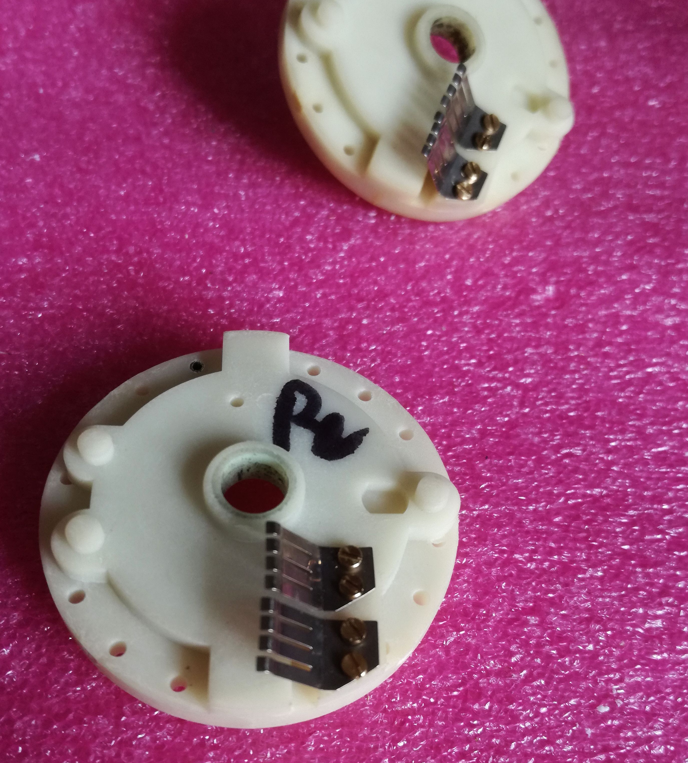
The frequency control – for some reason, there are different versions around, one that has wires attached, and one the has pins – interestingly enough, the 8565a control fitted has wires, but the 8569b requires pins – also here, good to have a spare assembly around, with the pins…
Defective bias pot – also here, a spare fitted.
Some of the contact fingers broken off-also there were fixed, and everything put back together.
Finally, noticed that the 10 dB segment of the 70 dB input attenuator (5086-7365) is stuck. Nothing dramatic, just one of the little O-rings holding the contact actuators broken off, and parts of it stuck in the contact.
Finally, a quick test – everything seems to be working-
-unfortunatly, still missing something – the sweep time indicator is not showing a time denominator (µs, ms, sec), and the analyzer remains in the digital mode for all sweep time settings – it should switch to mixed analog-digital mode (at the time the 8569b was designed, there was no easy way to run analog-to-digital converters any faster than a few kHz without causing exorbitant cost, so the 8569b uses the digital storage mode only at the slower sweeps).
Remaining items:
(1) Identify the issue with the sweep time indicator and missing transition to mixed analog-digital mode. Maybe related to the 8565a control fitted to a 8569b? – Checked by substituting a control assy from a good 8565a – working just fine with the 8569b – accordingly, this is not the reason for the fault. There seems to be a defect on the main front panel board. Maybe a bad switch contact, or a broken trace. Will be quite a pain to test will all the cables, switches and screws.
(2) Manufacture the control knobs for the frequency-bandwidth-span-atten-ref level setting. These were missing and don’t have spares at hand/these wheels are getting brittle anyway. Will make a new set from aluminum alloy, during next stay, in Germany, the only place with access to adequate machine tools.
HP 8569B Spectrum Analyzer: working essentials
After two very busy weeks, finally, a chance to have a look at the 8569B analyzer (with the 8565A control). No display, no way to find out if at least the essential items are working – these include the input mixers, the YIG filter and oscillator, and other GHz frequency components.
First tests showed that the power supplys are all working and well adjusted; still no display.
Connected a scope to the rear panel output – sweep is working!
Some little repairs of the CRT section (nothing really interesting to write about) – look at this sight:
Really great, a bright CRT, and well-focused. And, it is actually showing a signal – basically, a working unit. At least, a start. Now we just have to see how to get the controls fixed.
HP 8565A?? HP 8569B?? Spectrum Analyzer: a mixed box
For next to nothing, I got hold of a HP (Agilent, now: Keysight) 8565A 8569B mixed analyzer:
As you can see, the main unit, including the CRT and electronics, is a 8569B, but someone fitted a (rather incomplete) 8565A control assembly. Not a big deal, normally, but the control assembly fitted here has virtually all the common defects: missing contact wipers, and missing/defective knobs.
Another common defect (can all be fixed):
A quick test – the CRT seems to be working, albeit, it is now dark after a few minutes of operation – most likely, just a dead capacitor, but the CRT itself is definitely pretty good. Also the CPU seems to work just fine.
The unit has a lot of RF goodies, like a 22 GHz 3-stage YIG filter, a YIG oscillator, a 22 GHz mixer, various 22 Ghz coaxial relais – but with another parts unit already at hand, this unit seems to be to precious to scrap. Well, need to think about it, always wanted to provide an electronic replacement for the aging 8565A 8569A/B control assemblies. Maybe, a good project for next winter!
HPAK 8569A Microwave Spectrum Analyzer: some adjustments, an ultrastable 10 Volt reference, GPIB test- repair completed!
The manual for the 8569A describes a series of performance tests – not all of them were completed, but most. Fortunately, the IF chain doesn’t need adjustment. Still, it took nearly three hours to get the YTF tracking, the A/D converter/digital display section and other display related circuits adjusted. The log amplifier was carefully tested as well, all perfectly in tune.
The most amazing find – the internal 10.0 V reference was found at 10.00004 V. That’s +4 ppm – most likely, better than the voltmeter I am using to measure this.
The reference circuit, according to the datasheet, is uses a regular HP/RCA low noise opamp of the late 1970s (selected 741), and a +-10 ppm/K 1N827 temperature compensated zener. As it turns out – the actual part used is a 1826-1058, an OP-02 equivalent (0.65 µVpp noise, 8 µV/K drift), much better.
Resistors in blue frame are +-10 ppm/K tempco. Others are regular, +-100 ppm/K resistors.
The circuit layout – very much refined, a marvel of analog engineering – guard traces all around!
It is run at exactly 7.44 mA, using the 10 V reference to set the diode current – to minimize the temperature coefficient. See this diagram from the 1N827 datasheet:
Seems that after 34 years of aging, it is perfectly stable now.
Back-up of the internal EPROMs (4x 4 kbyte!) stored – just in case they fade out over time.
Last step – test of the GPIB functions – and, no issues at all.
Writing to the machine:
And receiving plot data back (two signals, close to 100 MHz, -10 dB):
At its final place, for now, on top of a 3585A – total of almost 200 pounds of test equipment. Hope the bench won’t cave in.