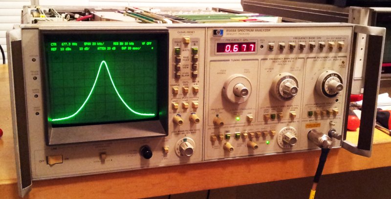
After fixing the display and front panel related issues (attenuator, “0 dB” indicator), the only major defect remaining so far is the tuning stabilizer circuit. Once the span is set to below 100 kHz, it is activated – and sets the unit to zero span, rather than the span selected, permanently. Only when the stabilizer is disabled (there is a button on the front panel), the span is back to normal.
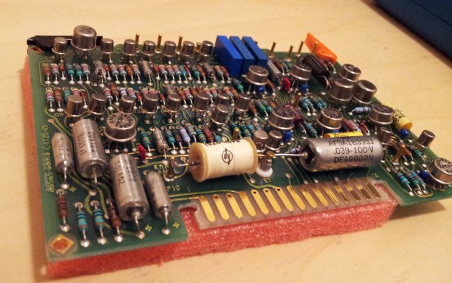
The source of this issue – most likely, the A14 tuning stabilizer assembly. Switched the board (part number 08565-60018) with the identical board of a 8565A – and, as expected, the zero span issue is gone!!
Now, we just need to fix the board.
The description in the service manual is actually pretty clear – the circuit uses a 1 MHz harmonic sampler, to keep the frequency of the LO stable. The initial lock is achieved by setting the analyzer to zero span, finding a frequency close to 1 MHz that represents a lock point. This frequency is controlled by a voltage, and a very long lasting sample-and-hold is used, than employs a special construction of a HP reed relay, and a PE/PTFE(?) lowest leakage capacitor – the white coil in the front, left, and the the capacitor, front, right – in the middle, a PTFE isolated post, going to a FET gate.
Certainly, a very special capacitor. Once this is achieved, error voltage of the sampler is used to steer the LO, and the analyzer is returned from zero to normal span mode.
The sequence of all these steps – controlled by a very interesting chain of transistors, resistors, and capacitors – nowadays, just a few lines of program code… but, nothing better than a handful of discrete high quality components.
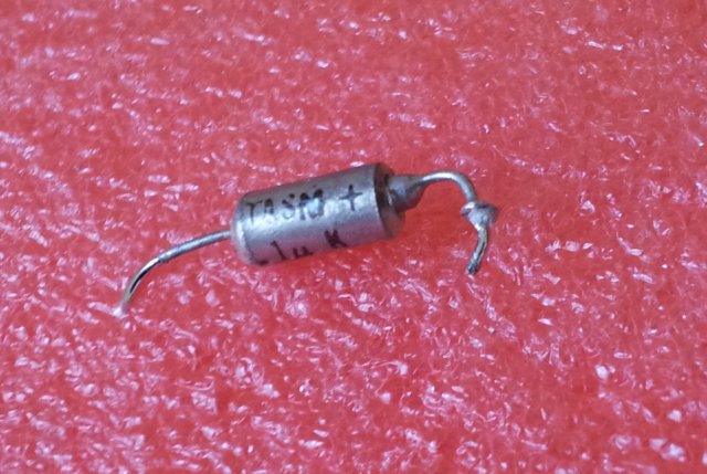
The “control generator”, see schematic below – it is not controlling the sequence properly – and, again, a defective cap. 0.1 µF (!), tantalum – red frame; a few 100 Ohms – near short. No way that this can get charged, and let the sequence proceed.

Replaced it, with a regular 0.1 µF cap (why did they use a tantalum??), and: A14 assy working again. 20 kHz span, 10 kHz resolution bandwidth. Working just fine – at all frequencies up to 20 GHz, the highest I can check here.
The black sheep (date code: 1980, week 7):
We can’t argue that they didn’t skim on parts – at the time, certainly, one of the best 0.1 µF tantalums available.
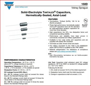
Parts list specifies 150D series, MIL–PRF–39003 mil-spec qualified high reliability hermetically sealed cap:


