
For those out there that need a good 10 MHz source to calibrate their counters – there is an easy method, at least in Europe – the DCF77 transmitter, near Frankfurt. It uses a 77.5 kHz carrier, which is kept very close to 77.5 kHz, all the time, and puts out about 30 kW of power. The carrier is controlled to within 2*10^-13, way better than I need.
To make use of these waves, I build a little receiver, using a tuned circuit, a FET pre-amp (which is located in a plastic case, several meters away from the bench, to avoid interference.
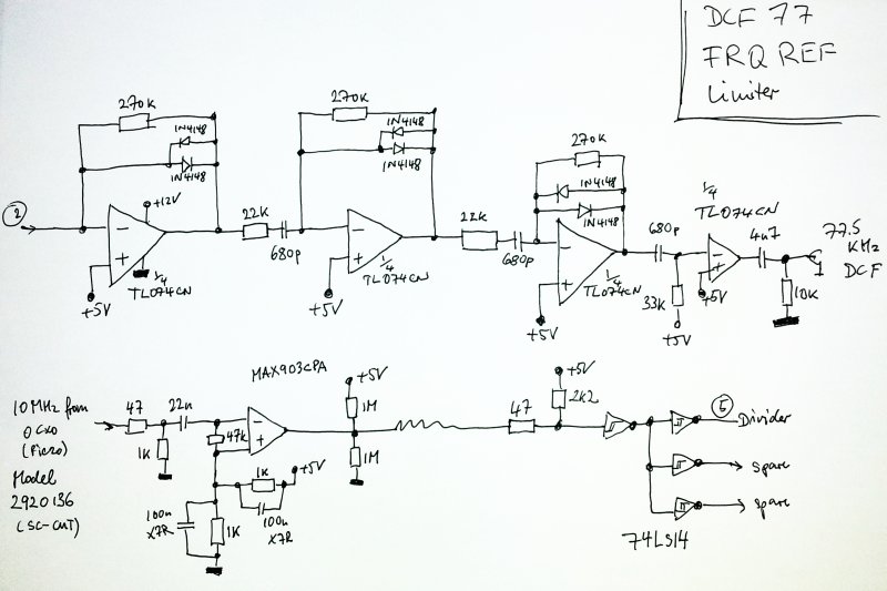
The 77.5 kHz signal is then converted to a square wave by a limiter circuit, and phase-compared to a 77.5 kHz derived from a 10 MHz OCXO. For the OCXO, I used a Piezo brand Model 2920136, but any reasonably good 10 MHz OCXO will do.
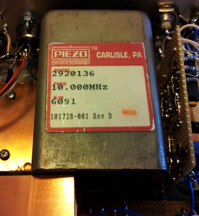
No need to go to a rubidium oscillator, which will only consume a lot of power and wear out over the years.
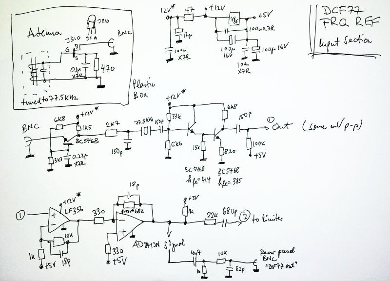
The amplified signal is also available at a rear BNC connector, for troubleshooting, and to find the best spot for the antenna (just connect a scope and align antenna orientation/place for best amplitude).
The tricky part – deriving a 77.5 KHz signal from a 10 MHz source. This requires a fractional divider. First, the 10 MHz signal is divided down to 310 kHz (4x 77.5 kHz), followed by two :2 dividers (74F74 flip-flops). This will give fast transitions, and exact 50:50 duty cycle.
The 10 MHz to 310 kHz divider is implemented using an ATMega8515 (you can use any other microcontroller that can handle a 10 MHz clock). The program does a simple trick – it generates 31 transitions for any 1000 clocks; and it does this with reasonably well distributed jitter.
7 blocks, with 33-32-32-32 cycles; and 1 block with 33-32-32 cycles; in total: 23 sequences with 32 cycles, and 8 sequences with 33 cycles – a total of 1000 cycles over 31 sequences. I am so glad that microcontrollers exist, this would have taken quite a few TTL circuits to realize this hard-wired.
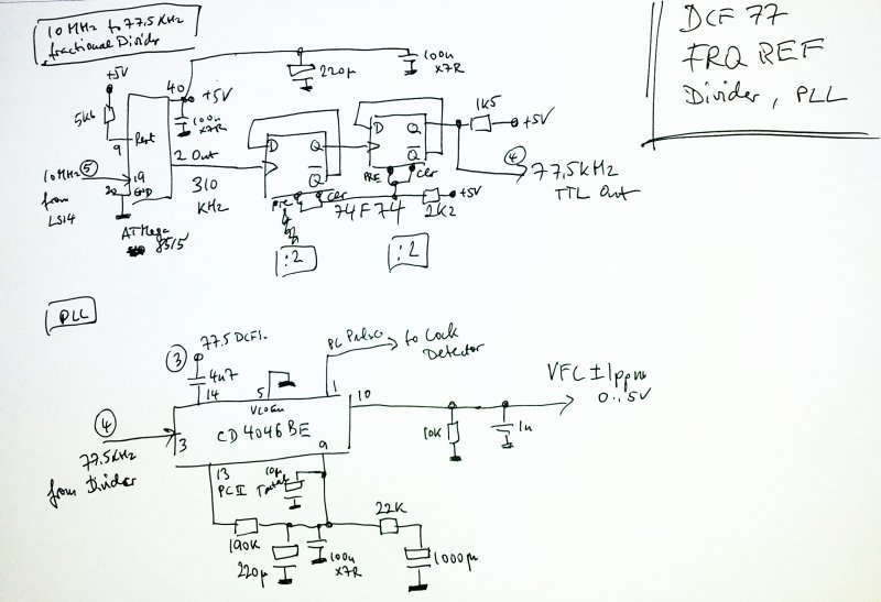
The PLL, build around a 4046 has a long time constant, several minutes, however, you could improve the frequency stability by using a constant of several hours – which is not quite practical, and also not necessary, for the given purpose (to provide a reference that is accurate and stable to better than 1 ppm, and that has a phase stability of better than a few microseconds).
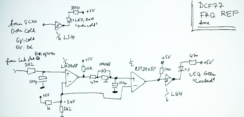
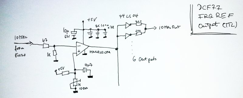
Some auxilliary circuits, for the lock detector, and the outputs. Outputs are TTL, but you can also add some transformers, resonant circuits, etc., in case you need other signals. I found these TTL signal very suitable to lock all kinds of test equipment, and never had any issues with ground loops so far. If you do phase noise measurements, I would recommend to use a local Rb reference anyway, or a free-running precision/low noise OCXO, not the output of this device.
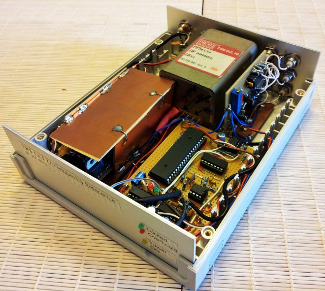
Note the shielding of the input circuit, using some copper clad board. A bit curde but works.
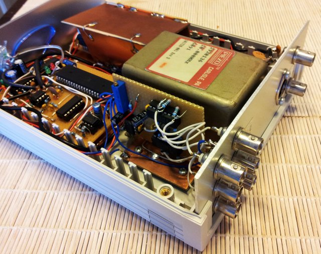
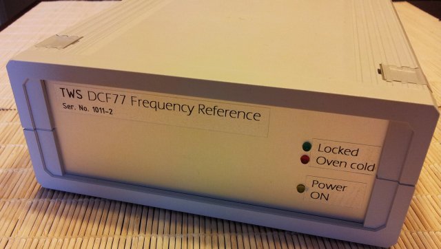
The thing, put into a nice box:
After some days of monitoring the output phase vs. a GPS-adjusted Rb oscillator – the device is working just fine. There are some phase fluctuations, most likely, due to the propagation of the 77.5 kHz waves, and these cause phase shifts of about 1 µs. Well, just temporary shifts, and by all means good enough to calibrate any OCXO to full resolution.
Why not use a GPS disciplined oscillator, or a Rb oscillator? Well, the GPS signal, who knows when they will shut it down; and it needs a rather facy antenna, and, you can’t build it from scratch (well, you can, but would be a major effort!). Why not a Rb oscillator, well, I actually have a good Rb, but rarely use it, because it needs so much power, and way too accurate for the general tasks at hand – rather have the DCF77 running, which only needs very little power and generates no heat; and, the OCXO won’t wear out so soon!
Interesting project. The only component i am worried about is the quartz crystal filter at 77.5 kHz. Where it can be found? Where did you find it?
Is this filter, or simple quartz, necessary? Have you done some experiments without it?
Many thanks!
It is only there to limit interference. It can be found in any simple dcf77 alarm clock. You can consider a design with no quartz, it does work and is even better from a standpoint of phase accuracy, but you will need more capacitors and tuning instead. Design should allow for no more than 100-200 Hz bandwidth in case you want to go without a quarz. Simon
Hello Simon, congratulations for your work!
Aout the “77.5 KHz crystal filter alternatives”: in your opinion would it be a good idea to detect the DCF77 carrier using a PLL/tone detector (i.e. the LM567) ?
Thanks in advance, kind regards!
Hi, it can definitely work but I doubt you get good amplification of the antenna signal without some kind of filter in the first amplifier chain. Probably, you could build a tuned opamp amplifier with about 300 Hz bandwidth to amplify the signal to a reasonable level and get rid of most of the noise, and then use a PLL-tone detector as a receiver.
you could also just use a fast adc and sample the antenna at 77.5 khz or similar to build your own digital receiver which is almost the same as a pll-tone detector.