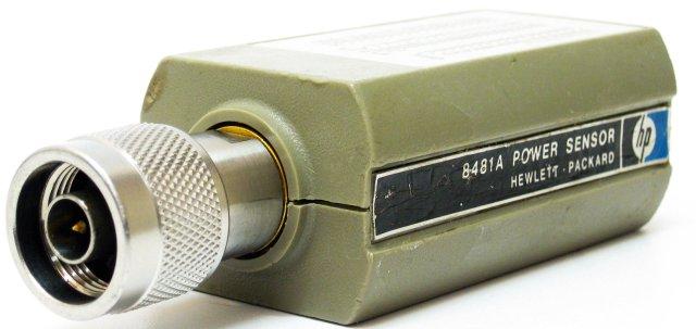
A remarkable HP product, the HP8481A sensor. It appeared on the market about 1974, and still today, these devices are very much thought after. It works from about 10 MHz to 18 GHz, -30 to +20 dBm.
Quite some detail about this sensor can be found in the HP Journal, 1974-09 edition (pages 19ff).
There is says that the sensor can withstand 300 mW power, and even 0.5 Watts for seveal days. Still, there are many sensors around that are blown – why do so many people connect them to 0.5+ W transmitters and destroy them along the way? I have no idea!
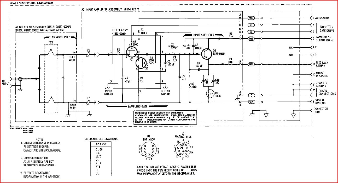
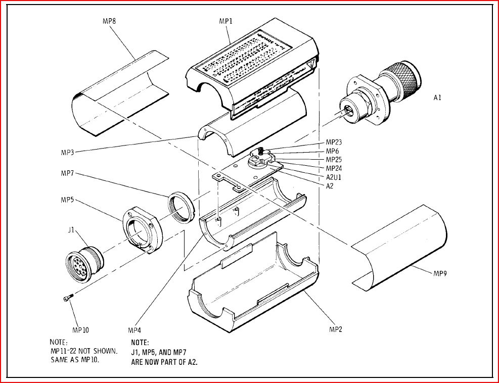
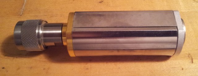
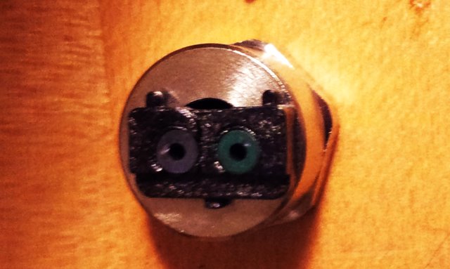
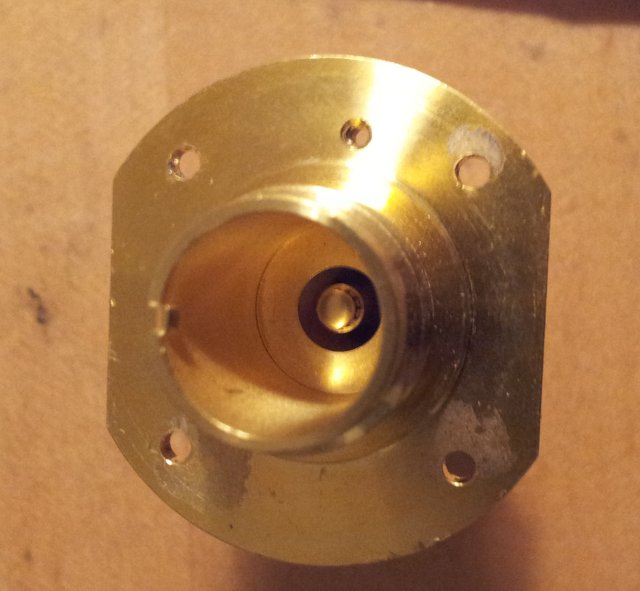
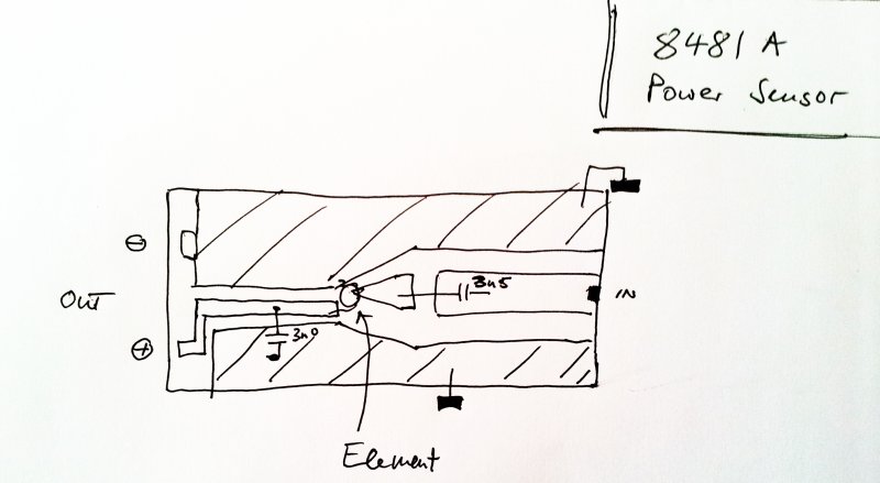
Here, a quick glance at the internals:
Note the capacity values – measures: 3.5 nF at the input, 3.0 nF at the output. This is all real gold on sapphire substrate!

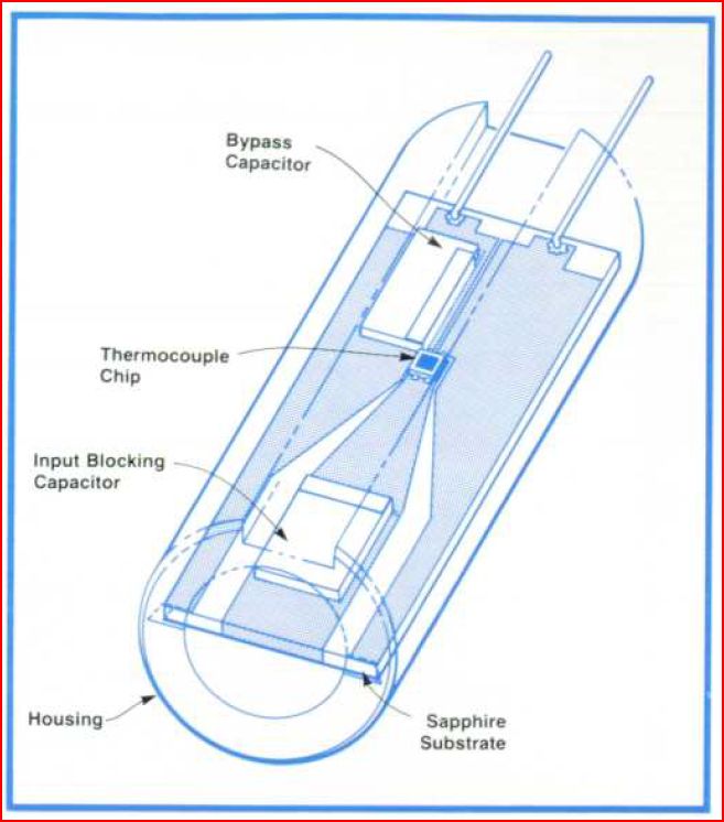
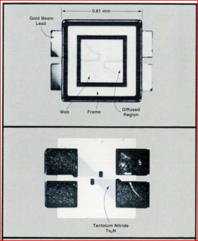
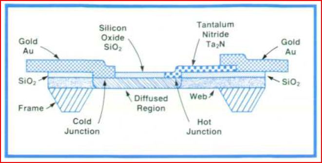
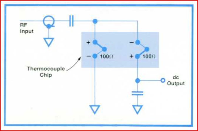
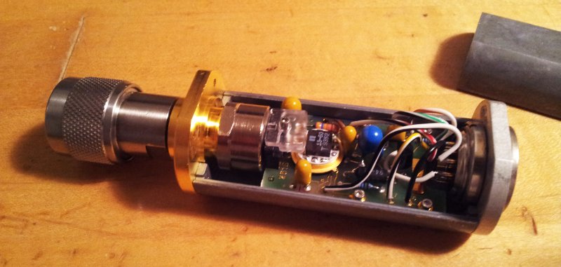
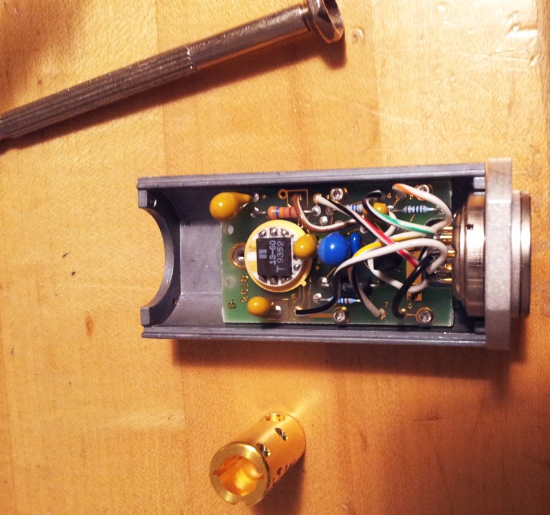

hi, I also found most of 8481a sensor are blown. but in most cases the two sensors are not both failed. so I guess it was partial repairable to shunt a 100 ohm resistor at the blown sensor.
BTW, I’d like to ask what size of screwdriver head suitable to uninstall the sapphire substrate from cylindrical housing? I found there are four screws. thanks!
Hi, I used a small Torx screwdriver, because I didn’t have a hexagonal/Allen key that fit (well below below 0.05″). Good idea to bypass one of the thermocouples. Will try to attach a 0604 SMD with some conductive epoxy.
I’m planning similar thing. I’d like to know what type of conductive epoxy you will use? I’m going to use some pure indium to solder a resistor onto substrate. I had experience that the gold on sapphire substrate was totally dissolved by normal Sn-Pb solder. Maybe pure indium solder could ease this phenomenon. Thanks.
Never tried to use indium on sapphire substrate (only used if for contacting ceramics-supraconductors). The conductive epoxy I can recommend is E-Solder 3021, it is not cheap, but if you keep it in the fridge (not freezer) it will keep well for a long time.
Thanks. Could the epoxy still have good conductivity in the several GHz and microwave frequency? I just purchased some pure indium and would begin experiment several days later.
Absolutely, conductive (silver) epoxy is also used by in industrial production, fo GHz purposes. I have mounted shunt diodes for 10+ GHz with this epoxy glue with no issues at all. If you can make the indium contact the resistor and pads well, I see no reason why it shouldn’t work. All you need is a steady hand!
How to measure if one or both of the sensor’s are defect?
will the 100ohm resistor do the trick?
the E-Solder is to expensive to repair just 1 sensor. an different sensor is cheaper.
Silver paste(solder) is an option?
Hi Rene, to measure if the elements are defect, you need to remove the sensor element from the device (which is a bit tricky, because of the gold wires, etc.), and then you can just probe across the chip with a regular Ohm meter. The two sensors, thermocouples, have a nominal resistance of 100 Ohm, but can’t be replaced by a ordinary resistor, because one is the active element for power sensing, and the other is used as a reference. Maybe if the reference is blown, and you replace it by a resistor, you could still get some readings from the power meter, with very much offset baseline, and accuracy would be gone anyway, but may still be usable for some test purposes. To replace the chip reliably, I think you would need to use wire bonding/ribbon bonding or similar. E-solder or other type of silver conductive glue may work for some few years on such substrate and geometry. Silver paste for soldering, I don’t think it will work because of typcially rather coarse silver particles.
I have seen SO MANY blown thermistor / thermocouple RF sensors in the past that i feel lucky to have two working units (HP8481A and HP8481D).
One reason why thermistor / thermocouples blow so easily is the low margin of safety these units provide. For example, the 8481A can measure -30 to +20 dBm. However, the “poof” level is 300 mW (+25 dBm) which provides a mere 5 dB margin, easily prone to human errors.
On it’s side, the diode sensor (HP8481D) measures from -70 to -20 dBm and it’s blowout level is 100mW (+20 dBm). While more fragile than the 8481A, the HP8481D has a MUCH larger 40 dB of safety margin.
The secret with the diode sensor is to always think of it as a “microvolt” sensor and to ALWAYS use it with attenuators.
Pesonnaly, i use two 20dB Mini-Circuits Type-N pads (very accurate in the sub-GHz spectrum). With this setup, especially 40 dB, a multi-watt overdrive will blow the much cheaper attenuator rather than the precious sensor.
I only remove the attenuators in a known low-level (verified with the attenuators before) environment.
For the 8481A, i also use attenuators to keep the input level below 1 mW (stay AWAY from the 100mW maximum reading level). Only when necessary and after careful verification, i go up to +10 dBm.
When not in use, terminate the sensors into small low-power 50 ohms loads. Do not use the attenuators since they make the unit large and more prone to mechanical failure.
RF sensors, (especially the diode ones) are static sensitve.
These sensors are so precious and useful, you can not afford to blow one.
73 de Normand VE2UM.
Thank you for the insights, I didnt know about the damage levels being so close. Normally the generators I use dont have more than 20 dbm, so no big risk, but I will be even more mindful when working on amplifiers. I do use attenuators with the sensors also to protect the connectors, only in some cases where high precision or full range is required I attach the sensor directly.
I had 1 sensor with a good TC chip and a broken gold lead on the ground side and a number of sensors with bad chips to experiment on.
I too have had problems soldering to traces on ceramics etc, however I’m fresh out of IC lead bonders and gold wire.
First try was the silver conductive conducting glue sold in syringes. Not strong enough – a total waste of time.
I ended up using a Zeny station instead of my Weller because I could set tip temperature other than a magnetically controlled 700C or 800C tip.
Starting at 390C was not quite enough 420C worked fine for me.
The tiny conical tip used on the ground side got the heat sucked out of it too fast to solder.
A small wedge tip about 2mm across worked fine to solder to the ground side and no problem with the gold coming loose from the sapphire substrate.
The original gold wire measures about 0.090” or #30.
I used silver plate #30 WW wire (the normal stuff we used all the time for WW).
I strip off an inch or so of the WW wire insulation, tin the end.
A dab of 0.030 solder on the iron tip and soldered the lead in place. This worked just fine.
Trim the end of the new wire to length of original lead with A1 set in place.
It works fine but I have no way to test accuracy / calibrate across the frequency range compared to the original gold wire.
There’s nothing to lose in repairing as far as I can tell.
It would be valuable to have someone with the calibration equipment evaluate performance of a sensor repaired this way to an original with bonded gold wire combination across the sensor frequency range.
Sounds like this had mechanical damage, maybe from being dropped. Good to known it can be fixed. I had some luck in similar cases with two component silver epoxy, and in other cases with some indium, which is a soft metal that sticks to ceramics very well and easily melts. The sensor should still be good for everyday general purpose, I would just check it for reasonable operation by connecting it to a sweeper and checking at various frequencies.
hello , years ago i ve remove one thermocouple from marconi 6913 and on back was written marconi d292 made by NOVA.
i ve bought a stock of Nova thermocouples from Aeroflex and i should be able to fix all this series , hope the 8485a 8487a have same chips inside .
regards, sebastien Corradi MET F5RYZ
http://www.metd.com