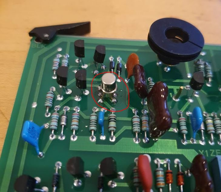
Shortly prior to my departure from Japan I started repair of a HP 4140B. A very desirable instrument for semiconductor characterization. The issue remained that output “A” didn’t provide correct voltages, probably due to some issues in the amplifier.
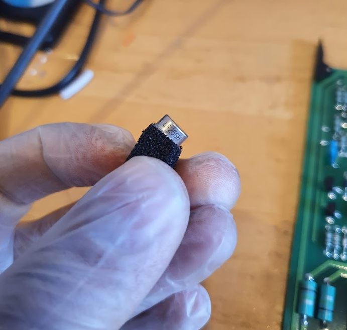
Two month later, I have returned to Germany, and a spare LF256 J-FET opamp had arrived, so I thought it would be a quick fix – but to no avail.
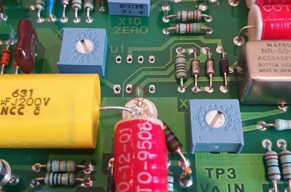
Fitting the LF256 to the board – I usually leave some part of the old wire in the Teflon isolator, because I want to avoid soldering/melting the solder in the Teflon part – it is all difficult to clean up afterwards, so I prefer to solder the new part to some leftover wire, rather than contaminating the isolator.
But- with the new opamp installed, same symptom, no proper output, current limit function of channel A blinking, but the input of the opamp is good. So it must be something else down the chain. Another look at the schematic…
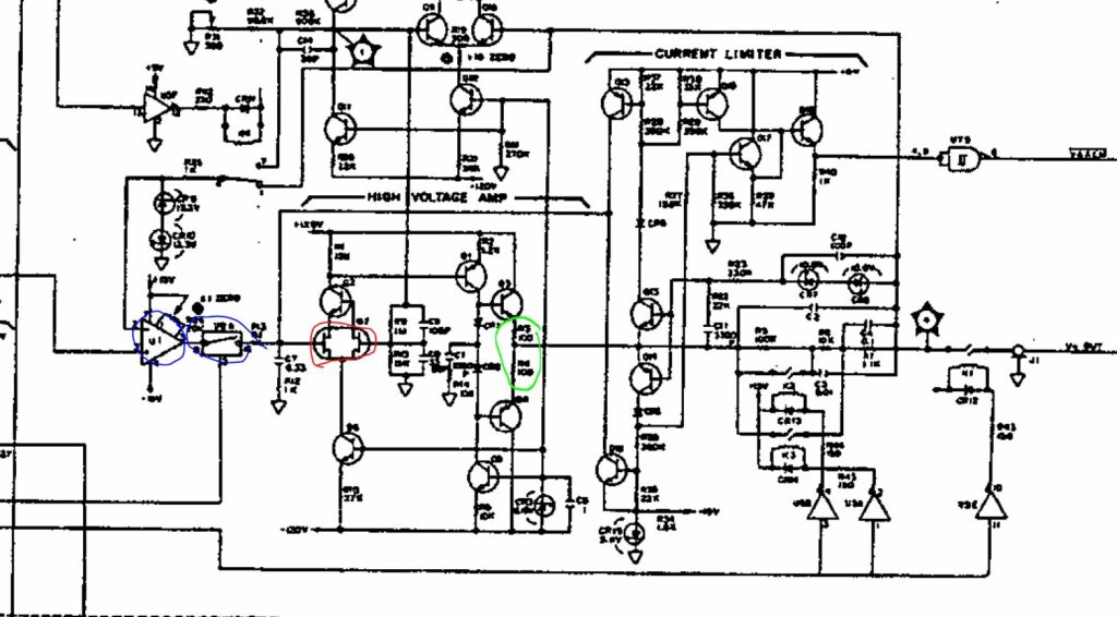
There is an analog switch, followed by a discrete linear amplifier with a dual J-FET input stage.
After some study of the analog switch (cutting a trace and checking it), the switch appears fine. Next in line, the dual J-FET, and in fact, this is dead – found it by measuring the E-B and C-B transition voltages with a diode tester (instrument powdered down and board removed!!), and the transistor around the FET shows largely different values compared to the working B channel. It is 1855-0049 HP part, available in some single piece quantities but expensive!
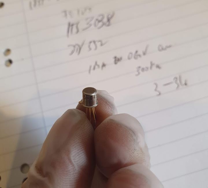
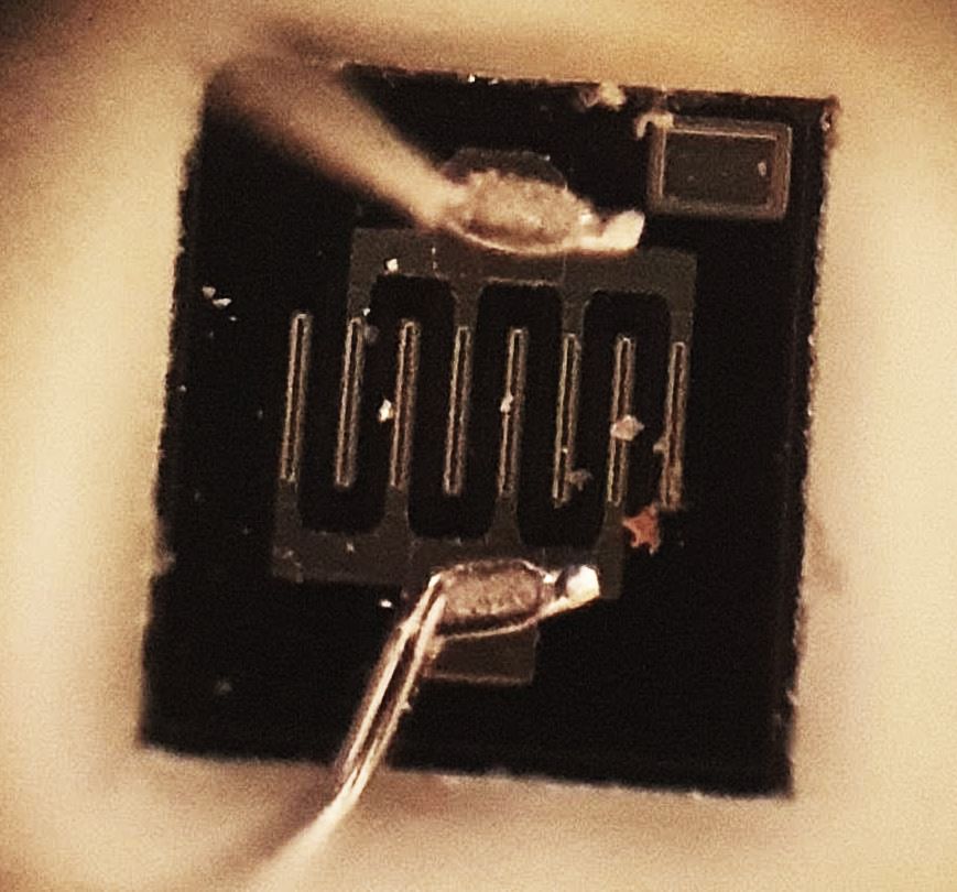
Looks still shiny and new, but it isn’t working.
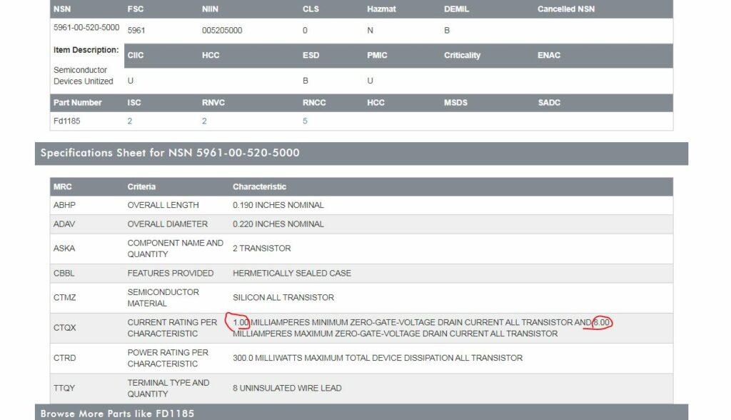
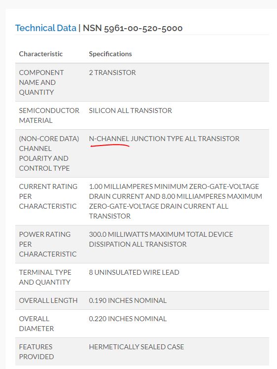
Studying some NSN databases, found at least some data of this part, which had been manufactured in equivalent versions by some other manufacturers as well, probably in the 1970s.
It is a rather not so special depletion n-type J-FET. But it is a dual FET part, and while single J-FETs are no problem to get, dual FETs are rare specimens.
Even in their long past days, these didn’t come cheap… maybe something like 40 EUR a piece in today’s money.
So we need to do further study, and there are essentially two kinds of dual FETs – some that have a specially made dual die, with both FETs on one chip and coupled in various ways to keep them from drifting apart with temperature, etc., and the other kind, which is merely just two reasonably matched separate FETs in one case, for convenience more than anything (and for thermal match).
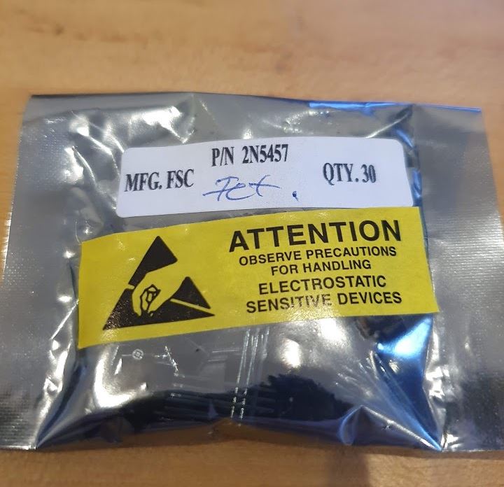
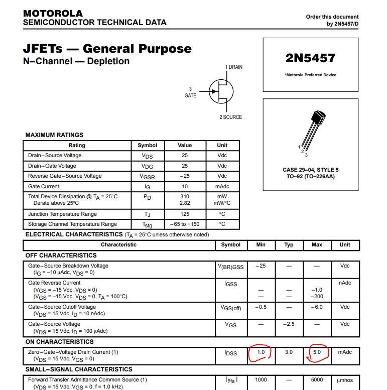
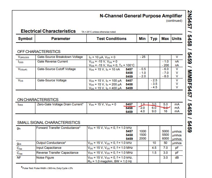
Screening through my inventory I found these 2N5457 FETs which have pretty similar electrical characteristics, in particular, zero-gate-voltage currents.
The parts I have are all quite uniform so there is no need to select a special pair.
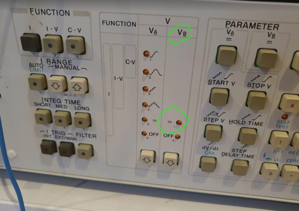
With such replacement with similar parts, rather than identical parts, I think it is a good idea to take no risk, so I took the B-channel dual FET and transplanted it to the A channel. And the B channel, which is anyway only a secondary function of the instrument and doesn’t allow the same fast ramps and functions like the A-Channel, it will be definitely good enough to install the two FETs separately (closely together), rather than the original part.
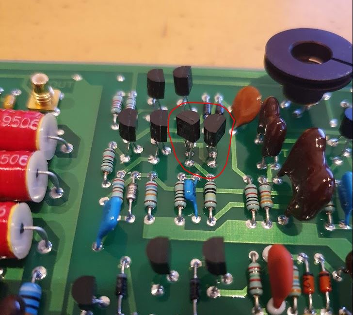
The dual FET of the B channel replaced by two 2N5457.
The B channel dual FET 1855-0049 transplanted to the A channel.
With these repairs, the instrument powdered on just fine, and the output voltages were spot on without any need for alignment. Even the zero bias setting if the LF256, no need to adjust.

