This little post may help those that are dealing with rotating or linear encoders, and have been wondering how to build a circuit that actually works, and with a degree of reliability useful for industrial applications. Around machine tools, and similar equipment that rely on such encoders, there is a lot of electric (and audible!) noise, so most hobby circuits that just take some TTL signals and do some quick stuff and calculations won’t work. Let’s try with a real circuit and some good code.
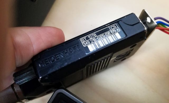
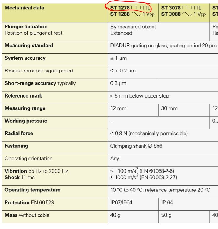
Here is the device, it’s a Heidenhain ST1278, 10x interpolated TTL output micrometer.
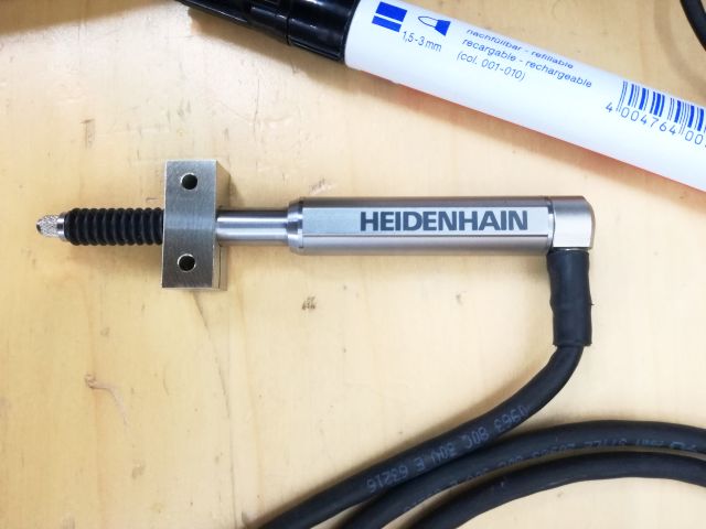
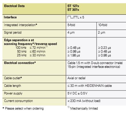
According to the datasheet, it has a 20 micron grating, which will lead to a 2 micron signal period, allowing us to get 0.5 micron resolution.
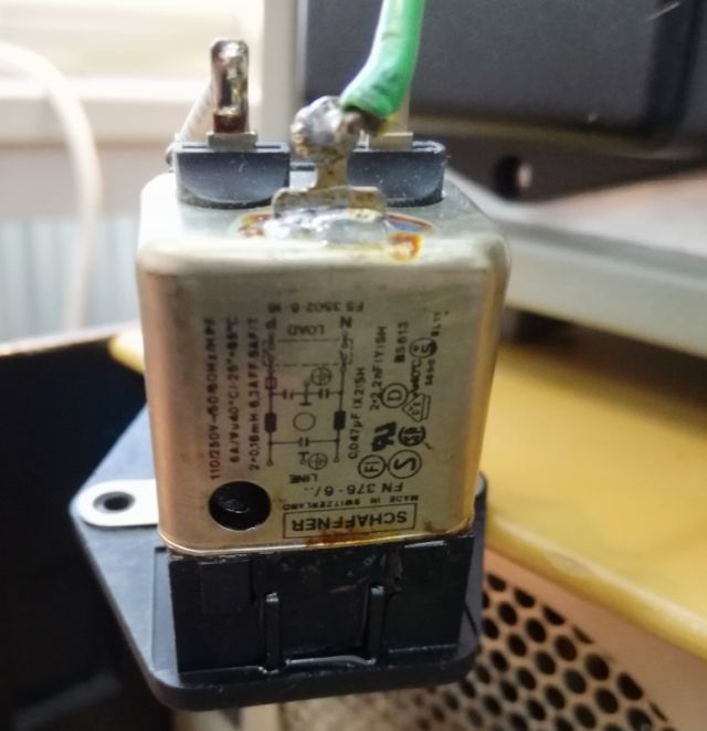
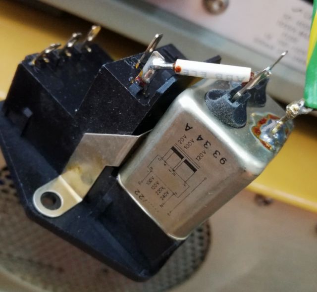
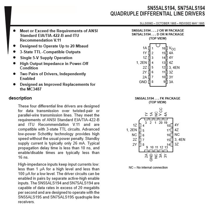
After carefully opening the plug, which has the Heidenhain logo, and secret Heidenhain electronics inside, I can tell you, Heidenhain uses a 75ALS194 line driver, to drive the RS422 output.
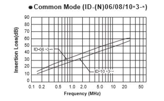
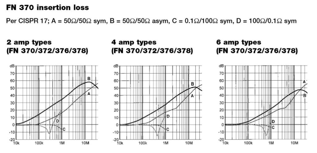
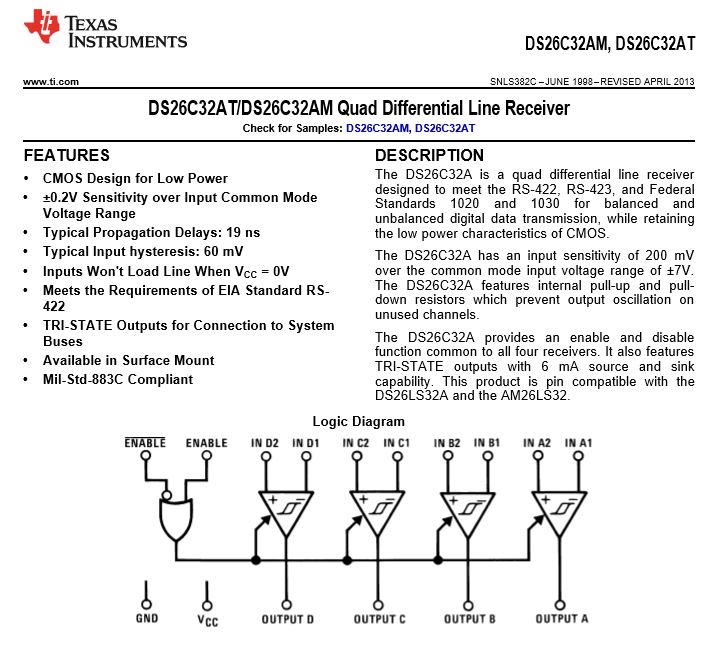
We will be using a DS26C32ATM line receiver, to get the differential signal converted back to TTL level.
The differential lines is terminated in 120 Ohms (watch out for their dissipation, if you consider building this in SMD), and has two 220 pF capacitors to absorb and high frequency noise. This thing is running at 100 kHz max.
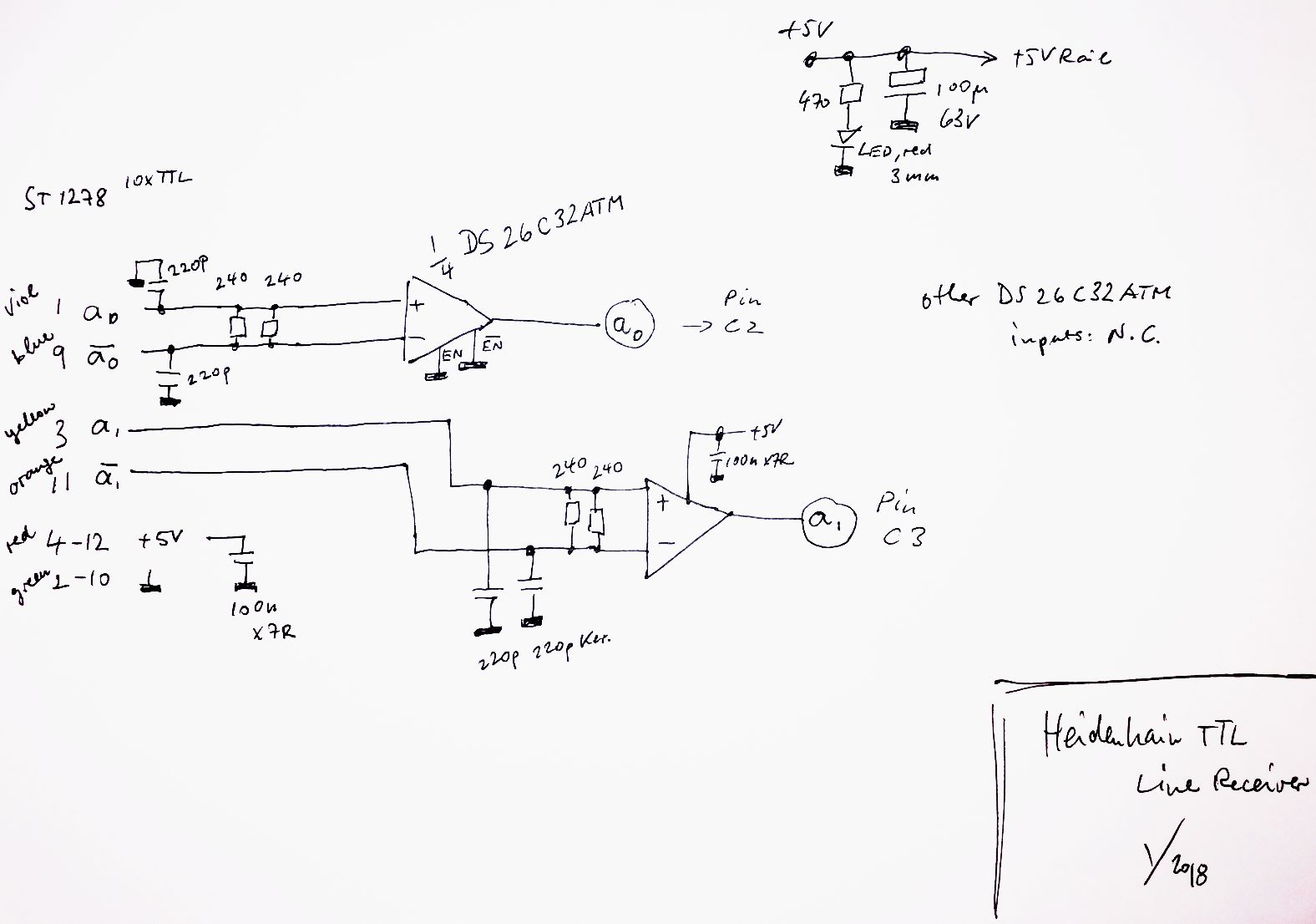
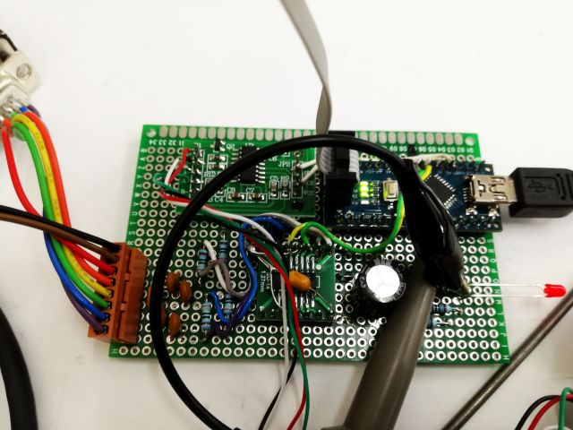
The output of the DS26C32 is going right to a ATmega328P, sitting on a Arduino nano clone, for convenience. This uses the common CH340G seriell to USB converter to talk to a host computer.
This is the full board. USB power is enough, even for the Heidenhain, and a HX711, which is also used in this device, for other purposes.
How to get the Heidenhain signals decoded into position. Well, we follow a sampling approach here, rather than using any of the rising edges, triggers, etc. – we just sample the two Heidenhain lines at 125 kHz, and compare the sampling result to the last result (of sample N-1), to determine if the Heidenhain moved forward, backwards, or not at all. If both lines change status -we know that something went wrong (e.g., if Heidenhain is moving to fast, or if some noise comes in despite all the effort to keep the noise controlled by the high current differential line).
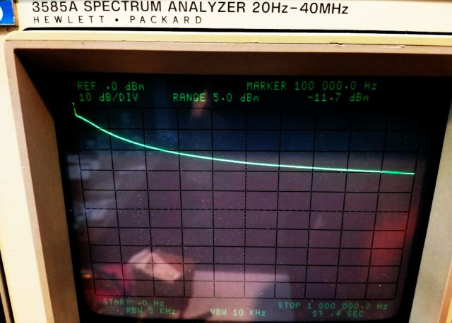
The 125 kHz sampling is running on a timer-triggered interrupt routine. The duration of the interrupt can be monitored -at least in debug mode- by watching a test pin of the mega328P, by setting the test pin high when the interrupt is called, and clearing it once the service has been completed.
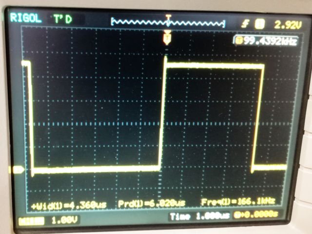
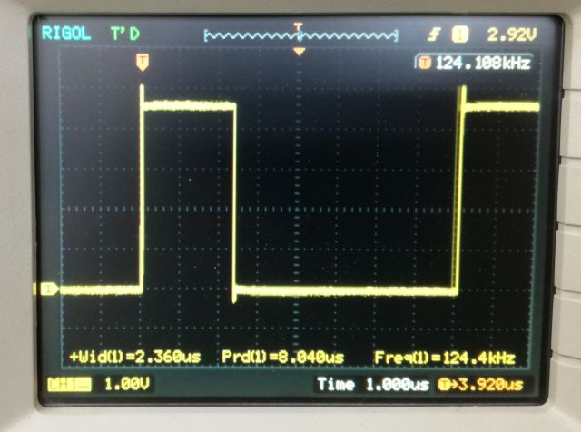
The initial software still used more then 4 microseconds for the sampling, a bit too much, this can be reduced to 2.4 microseconds, even without any special tricks.
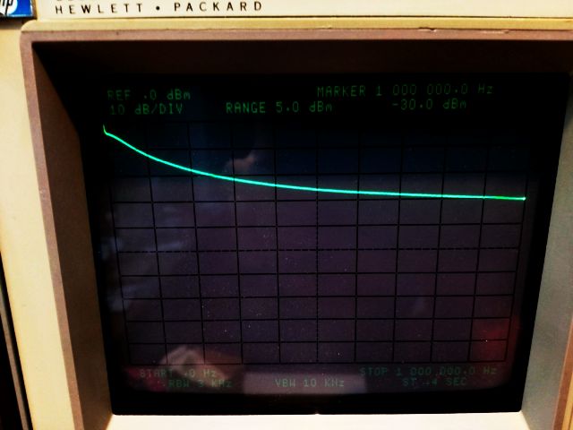
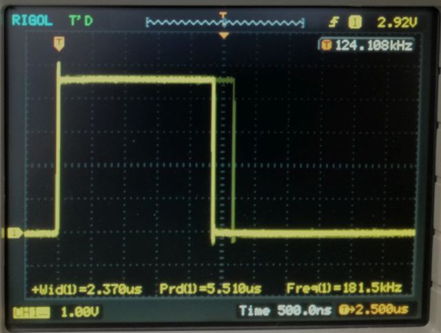
Below, you can see the effect of a sampling error (introduced by very quickly pushing the sensor arm inwards), it takes slightly more time to handle the error.
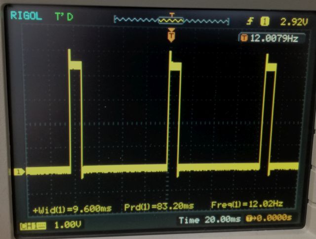
Finally, all that remains is to communicate with the host – this is done at a data rate of 12 Hz, plenty for this application. The data interval is triggered by the HX711 load cell converter, and the the full dataset, including, current encoder reading, error count, load call reading, and time-stamp are transmitted to the host all in one packed, as hex encoded data, and at 19200 baud. All pretty fail-safe and slow, but working just fine, and still a lot of idle time on the line (see transmission pattern on the scope below)!
Below, the avr-gcc code performing all these wonderful tasks.