
There are many circuits around in the web, related to GPSDOs, and a more sophisticated design with a self-steering u-blox receiver has been published earlier here. Now I felt tempted to try an easier approach, without the hassle of precision references, operational amplifiers, DAC, and other devices that are great but high cost when you need to avoid noise and other complications.
Essentially, this design is a clean-up PLL, with some monitoring of the receiver, and the PLL health. All monitored by a simple 8 bit microcontroller, an ATMega8-16PU in this case.
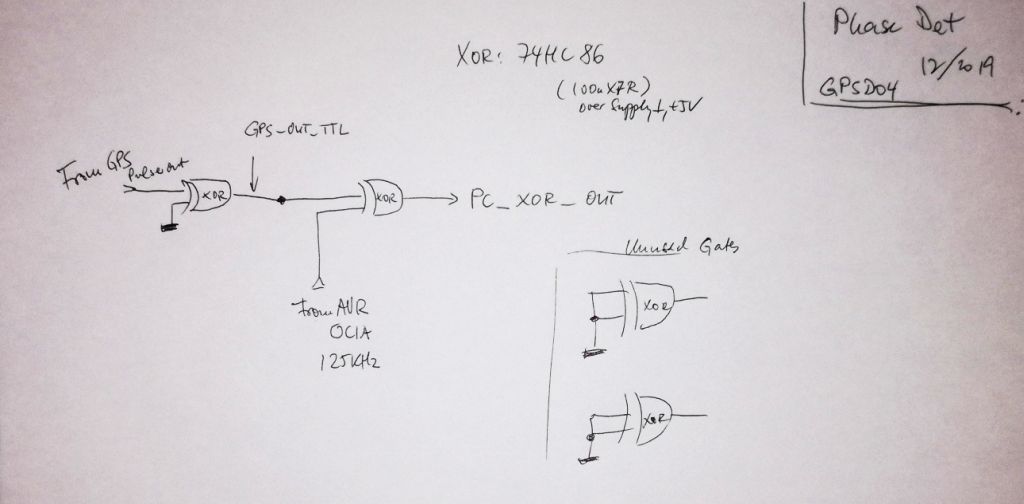
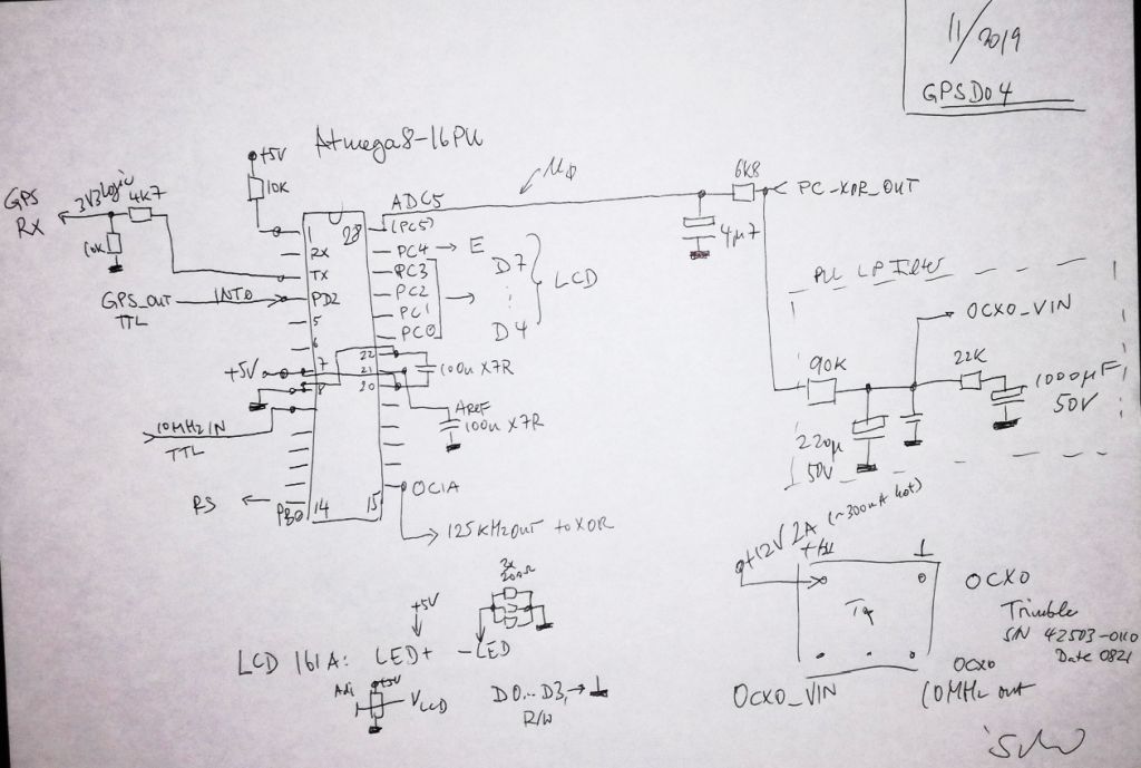
We have some elements here, (1) the OCXO and amplifier, distribution amplifier – to provide the outputs, 4 in this case, and a good TTL level 10 MHz signal for the PLL, (2) a u-blox receiver, configured to provide either 5 Hz flashing in non-locked condition (no GPS reception, or no good reception), and 125 kHz, 50% duty cycle as a phase reference in locked condition, (3) the MCU, ATMega8, that is configuring the GPS received, providing a 125 kHz signal derived from the 10 MHz OCXO (the OCXO is used as the microprocessor clock – don’t introduce a new clock in such circuits, which will only lead to spurious signals!), (4) a 74HC86 that is used as a phase detector, and to convert the GPS output (a 3.3 V signal) to 5 V level.
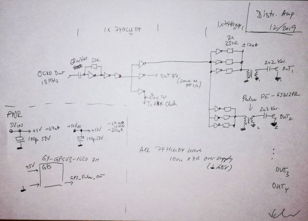
That’s the OCXO and distribution amplifier…
The phase detector…
The controller and PLL filter – a simple two pole filter. It replaces all the expensive references, DACs and opamps of the more sophisticated designs. There is another small, faster filter to convert the phase angle to a voltage – converted by the 10 bit ADC of the ATMega8, 1 bit is about 4 ns.
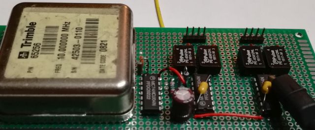
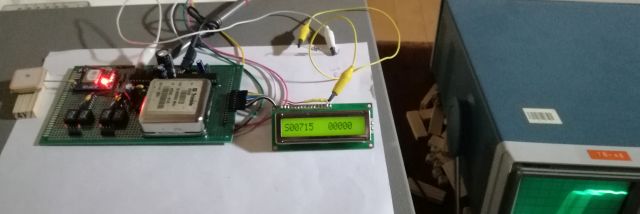
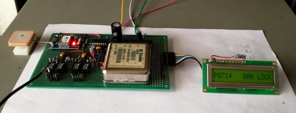
The circuit full view…

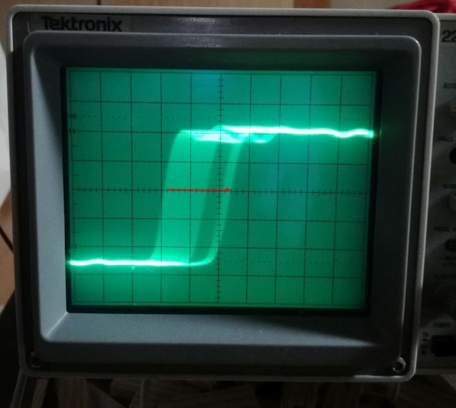
Some first tests turned out well. Monitoring the OCXO phase with a scope…
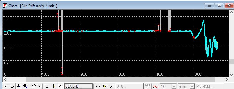
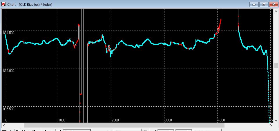
To do a more thorough tests, without all my various test gear that it back in good old Germany, I used the 10 MHz to run another GPS receiver (after upconverting to a 26 MHz clock), then the NAV-CLOCK message can be used to report phase and drift. The short term stability of the OCXO is better than the GPS, as can be seen, but there is no long term drift – because the OCXO is now steered by the 1st GPS receiver via the PLL (XOR phase detector and loop filter).
The phase detection is done at 125 kHz, a convenient frequency for precise measurement, and high enough for filtering.
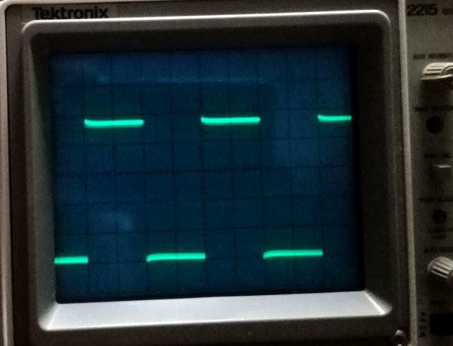
About 20 ns of jitter are clearly visible in the u-blox output, because it is running on a 48 MHz internal clock.
The circuit is running well, because of the few parts the cost is low and should be easy to reproduce. Let me know in case you need the ATMega code (written in GCC).
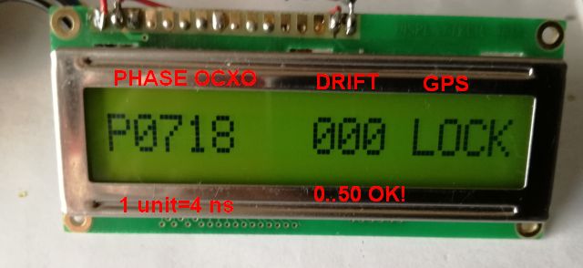
The display shows the phase angle, essentially, the duty cycle of the phase comparator output, the stability of the OCXO voltage (by a low pass algorithm), and the lock condition of the GPS (detected by measuring the frequency with timer0 of the ATMega8, and the INT0 interrupt at rising flank to reset the timer).
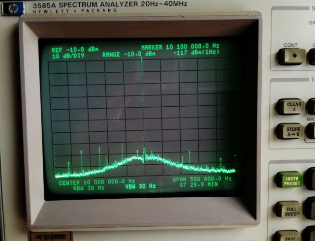
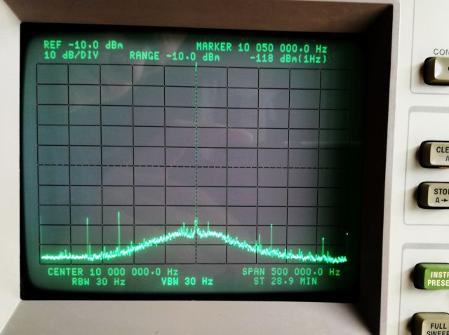
Phase noise is very small, there are no visible spurs (the lines seen on the screen relate to recalibration events of the analyzer rather than spurious signals, except those at +-125 kHz – at -90 dBc – probably you can get rid of these by better shielding and compartmentalization).
Sure there could be more sophisticated phase noise measurement, by analyzing the control voltage with a low frequency analyzer. I may proceed with such analysis these days but don’t expect to find much, anyway, would be best to fit the circuit to a shielded box first.
All in all, I believe this is a very workable solution that will give you great performance at lowest cost, and with little effort. Sure it will work with various types of OCXOs, the Trimble unit used is generally very good in terms of drift and phase noise. Be aware that some newer Trimble units aren’t all that good. The OCXO draws about 2 Amps at 12 Volts upon startup, but it is OK to start it with a current limited supply, at about 1 Amp, if you don’t want to overdesign the power supply.
Hi Simon,
Thank you for posting this very interesting solution.
I would like to learn how you did what you did, so could you please send the source?
Many thanks in advance,
Paul
Hi Paul, sure, will send it to you! Simon
Hi,
I really like the interesting and simple design of your GPSDO 🙂
As I am currently doing a SDR project and need a very precise frequency/time reference, this is perfect!
I have a few uBlox M8T laying around which I can use I suppose 😉
Could you also provide me the AVR code? I am planning to do it with STM32 but it would be nice as a reference.
Thanks in advance,
Christoph