HP 8662A Synthesized Signal Generator: almost fixed!

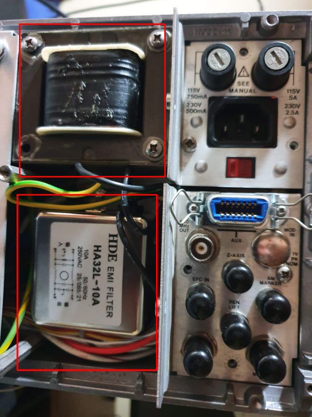
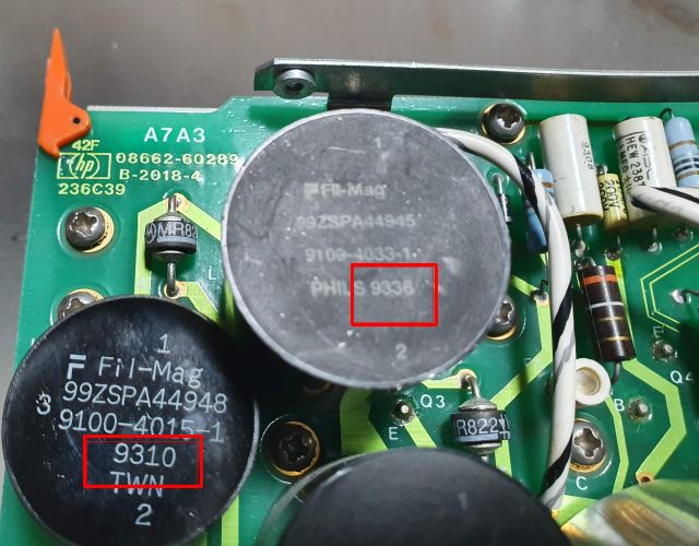
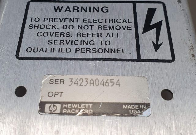
Still working on the 8662A, a unit that is in very good shape but someone tampered with the power supply in a non-expert attempt to fix it.

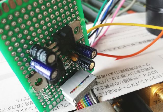
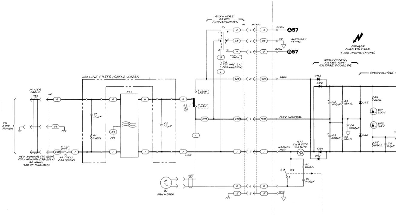
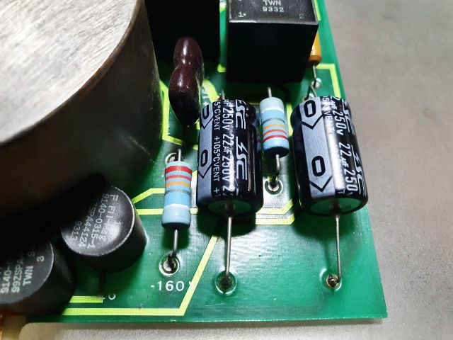
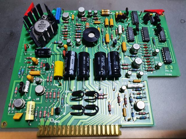
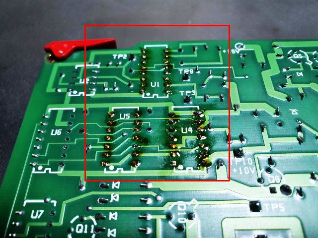
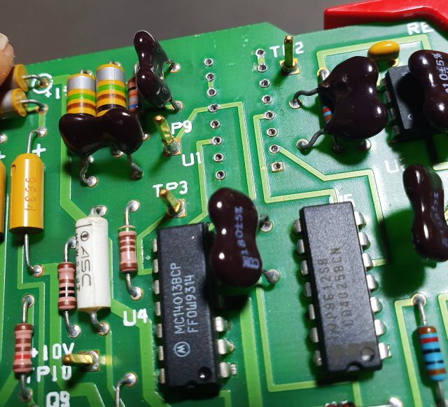
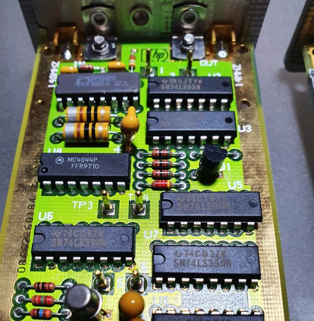
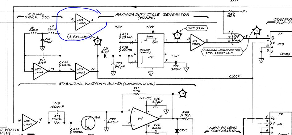
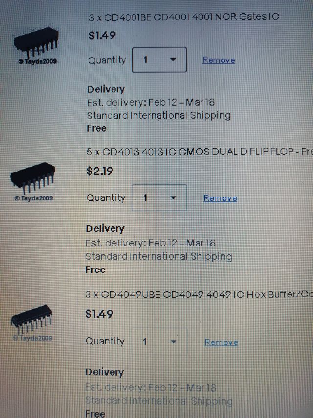
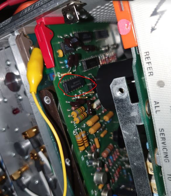
After a little bit of waiting, CMOS ICs worth a few dollars arrived, and a single 4049 CMOS fixed the power supply. Probably, the defective caps on the power converter board destroyed one of the transistors, and then lead to a voltage spike that destroyed the CMOS (which has a connection to the sense line) – only that gate got destroyed, the other gates still work.

There was no need for any adjustments, the voltages are still accurate to the resolution of the meters I have around here.

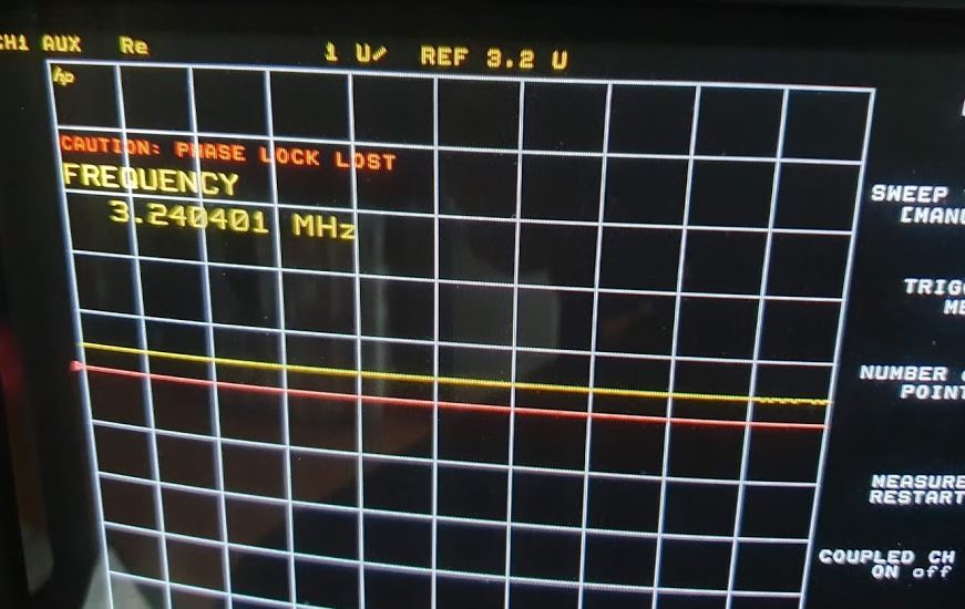
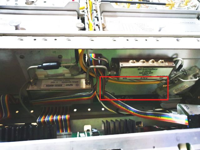
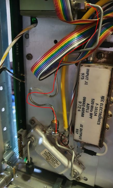
Back up and running, the machine is working fine and giving good output. At least after installing a coax line to bridge the missing attenuator.

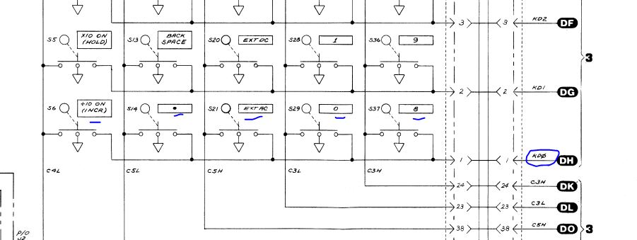
There are some small issues that were easily fixed. A few non reactive keys that were traced to a bad contact of the connector related to one of the lines of the key matrix.

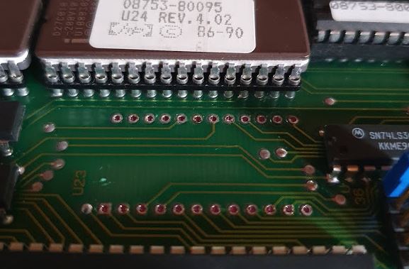
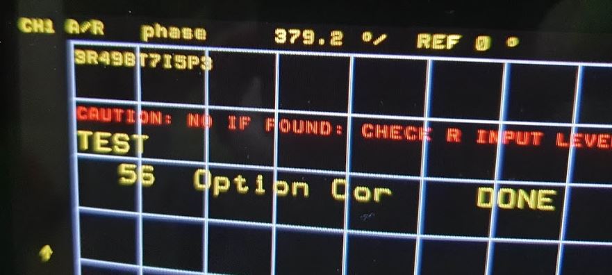
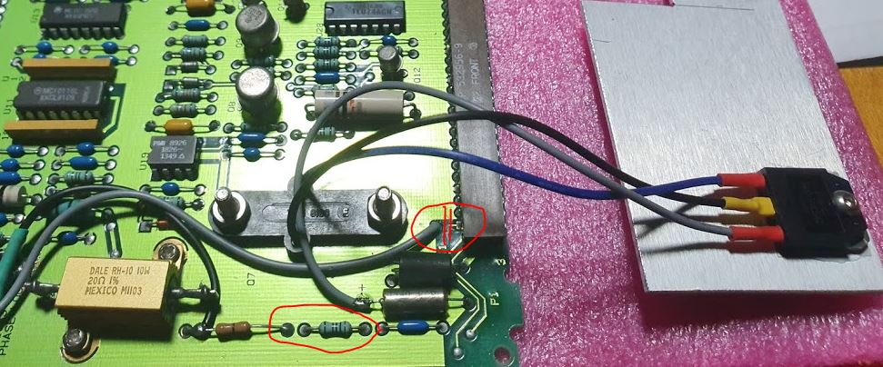
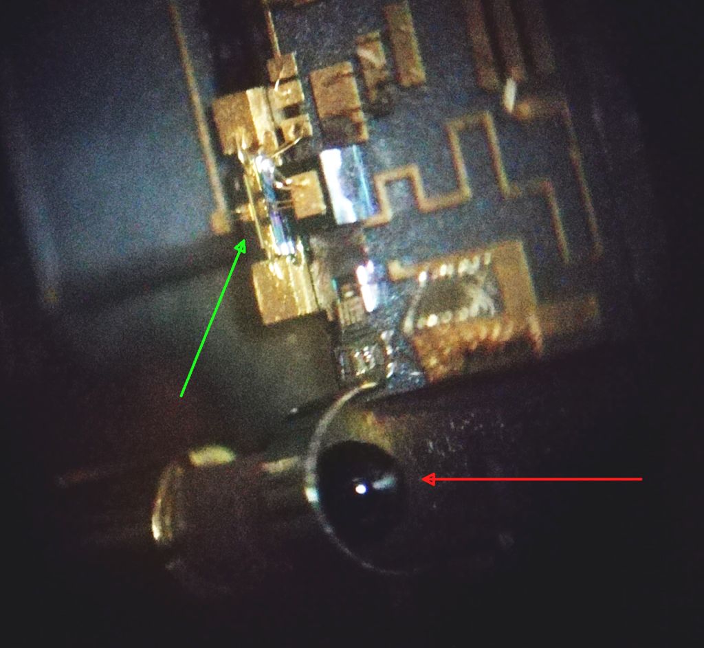
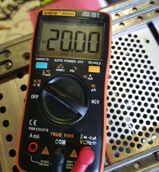
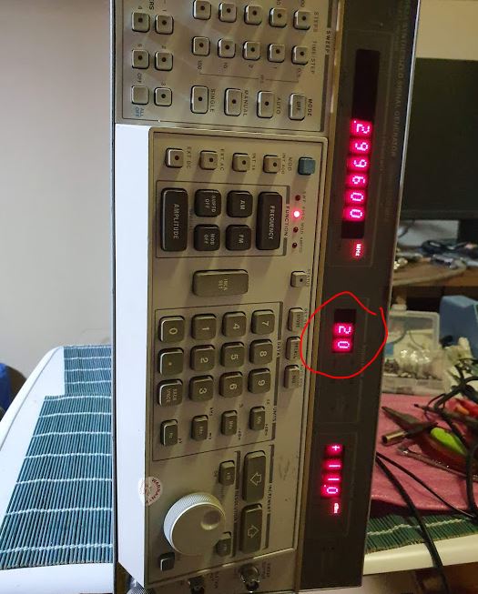
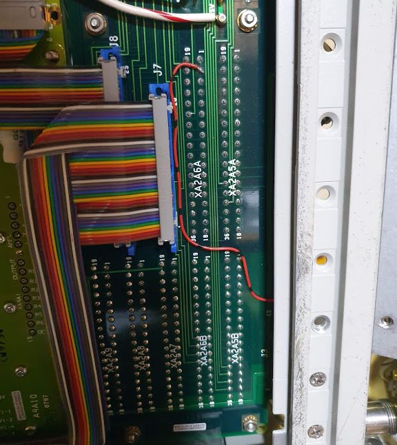
… and some issues of the modulation display. It is stuck at “20”, but the 1st digit (+-1) is working. Turned out to be a defective trace of the multilayer motherboard. Maybe someone damaged it by pulling on the ribbon cable, or similar bad handling – it is one of the outermost pins.

Easily fixed with a wire and some silicon glue.

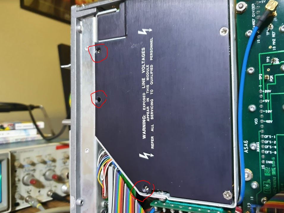
Some study on the attenuator – to my great surprise, the 8662A uses a retrofit set, to replace the obsolete attenuator at the time of construction of this very late production unit. And, it does not(!) use the attenuators of the 8663A. These don’t fit, neither in values nor in size, because there is an interference of one of the SMA connectors with the bandpass filter that is also mounted to the inner front plate. The missing attenuator, a 33321-60026 is a 85 dB unit, one segment 5 dB, two segments 40 dB each – these are switched simultaneously. A really special part, and difficult to assemble even if you have several other step attenuators because of the length of the 40 dB chip…

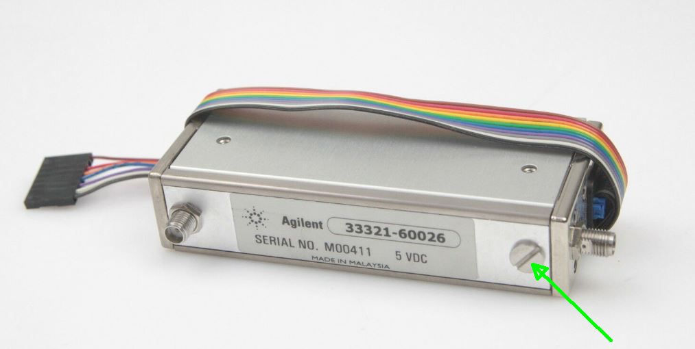
I don’t actually need to attenuator that much, but luckily found this set on ebay from a seller in Israel. The kind guy offered it for a very reasonable price, great! So we can restore the unit to full function.

Meanwhile, the attenuator set has arrived in Germany, where I will pick it up during the next business trip – coming up soon. In any case, I will also need to pick up numerous screws, because the unit arrived with several screws missing, even some quite essential ones.

Anyway, there are plenty of HP screws around.

HP 8753C Network Analyzer: Serial numbers, options, EEPROMs

The HP 8753C comes with some software options 010, time domain (essentially, a built-in FFT function), and the even more useful harmonic analysis, option 002. These work without any further calibration, and used to be available as a code to enter to the instrument , with service function 56, to update the option status.

Thanks to a kind gentleman, such codes are available now, and normally you can add them to the 8753C without any expert knowledge and risk.

Unfortunately, for this instrument, the method to add options by code entry didn’t work. How come? As much as we know, the option code depends on the serial number, let’s check if the serial of the CPU board is the same as that of the instrument (ending in 00860). A first hurdle, how to read the serial – it is not showing upon startup for the 8753C, but you can get it by first executing service function 55, which will fail, and then go to Display-Title.

To my big surprise, the serial shown is incorrect, only 4 digits, missing the “8”.

Accordingly, we need to dig deeper, and the serial number and other information is stored on the U23 EEPROM, a 2kByte chip, Xicor.

It is a very long lasting device, no reason to believe that it will fail anytime soon, but there are always risks. First, I read all the coefficients via GPIB, and then carefully desoldered the chip.

Actually, desoldering went very well, even just with plain tools, a soldering iron and a manual solder sucker.

The programmer, put together from a few jumper cables, and an ATMEGA128A board. When reading, I hardwired the WE- write enable input to VCC, to make sure that no data are lost. There are also 6k8 pull ups directly on the ZIF socket, to make sure the input stays “High” even if the jumper wire is not connected well.

In the EEPROM, clearly there is the incorrect serial, it is not actually missing a digit, but has an incorrect character. Maybe it got modified when the CPU clock failed (remember that this board had a bad osciallator?

Now, we need to put in a single character, an “8”.

I don’t normally need to program 2816 EEPROMs, so rather than taking chances with some incompatible programmers, I made a small program, to just set a single byte, at a given address. In this case, writing an “8”.

With the serial number corrected, put the EEPROM back onto the CPU board – using a precision socket.

Using the secret code that only works with the matching serial – and with the write protection of the CPU board disabled – the option install worked perfectly fine.

Now, the 8753C shows the options upon startup, and the time domain and harmonic analysis functions show up in the menu as softkeys.

Afterwards, I checked the EEPROM contents again, there are only 3 bytes changed, in-line with what can be found in online forums. Also tried to activate the 006 6 Ghz option, not much use for me, but the option code is same as seen for the 8753D, etc. There are 3 bytes, right in front of the serial, with the upper half-byte bits all set (0xFx), and the lower half-byte encoding the options in a bit-wise fashion. With no options, the three option bytes are all zeros 0x00.

If you need any of these EEPROMs or related advise with the 8753x units, just drop me a line.

HP 4192A LF Impedance Analyer: a few final fixes, and 14(!) EPROMs copied

Finalizing some repairs on the 4192A – there were two tasks remaining, replacing one of the front buttons that were damaged, and making a copy of the EPROMs, because none could be found in the web and the various forums.
The EPROMS are MB2516 type, 1982 vintage, with a white ceramic package and gold pins. Better not damage them, so I removed them after good sleep and after a cup of coffee, using some good tools.

Reading such old EPROMs can be a bit tricky with modern programmers, so I didn’t want to take chances and used a custom reader, reading every address several time. No uncertainties showed up, all reads identical.

The serial, suggesting 1981- vintage. According to the date codes, made in about 1982.

Just in case you need a copy, see here, hp4192_eprom.

Next, the defective button (at the left display) – did a thorough search in the German workshop, but no such button around (a dark brown, LED type button cap). But I did find a “LCL” labeled button. The original 4192A “Local” button has no print, so I did a little swap as indicated on the picture. Now all looking good.

To handle all the data and sweep function of the 4192A, best to use it in combination with some software. Fortunately, there are some great tools available for free, working right out of the box.

A set of resistors, left side are my 0.01% precision resistors (using them for calibration and adjustments of LCR meters), Vishay S102C/S102K, AE (Alpha Electronic) XT series. Next to it, some other resistors, all 1 kOhm.

The precision 1k resistor…

A 68 nF ceramic cap…

1 k low cost axial resistor…

1 k standard good quality metal film axial…

1 k metal oxide 4 Watt resistor (green, POS400 Vitrohm series) …

All in all, the 1 k resistors have very little parasitics up to 13 MHz, say less than 1 pF parallel capacity, and inductance, below what can be reliably measured.

HP 8753C Network Analyzer: an Avantek fix

Still continuing on the repairs of the HP 8753C. No luck with the Watkins-Johnson YTO, maybe one could get it to work after some severe modification of the phase lock assembly, but this is not my intention. So I rather try another YTO, a Avantek part, purchased for 25 USD.

Some changes are necessary – at least the dampening of the YIG needs some work. Set the 8753 to the source tune mode, and determined the capacitor value to get stable current regulation (in the source tune service mode, the PLL is open).
From about 100-120 nF onwards, in parallel to a 100 nF-2.2 kOhm network, perfectly stable. Added 200 nF, ceramic capacitors, directly at the YTO coil, and modified the R-C network on the A11 assembly a bit (replaced the 1 k resistor with a 2.2 k).

Here a quick schematic, the voltage regulators, and a few Zener diodes to protect the YTO driver. The main modifications are:

*1 cut a trace on the A11 assemly, re-route to the current sense resistor, to allow for some adjustment (sure you can use fixed resistor, once the necessary current has been found.

*2 replace the current sense resistor – most YTOs have 50 mA/GHz current requirement, about double of the original part.

*replace the YTO driver transistor, with a part that can be more suitably mounted on a heatsink, or provide some heatsink to the existing TO-3, if you can manage.

*adjust the R-C/C network across the YTO main coil, good values are 100-200 nF in series with 1-5 kOhm, in parallel with 10-250 nF. Check for clean and fast current regulation, with the PLL open (source tune mode in the service menu).

After the preliminary checks (adjust the current of the YTO for about 4 MHz output, with the source tune mode set to 300 kHz), immediate success – there are absolutely no PLL issues, phase lock is established smoothly.

There is a 3 dB pad, the YTO has plenty of power, and it will help to reduce any frequency pull.

Below, to adjust the pretune DAC, you need to remove the EEPROM write protection, this picture from the web is quite useful.

At first try – the pre-tune test passed!!

Even better – all internal test passed!

Some check at 1 GHz, the spectrum looks clean, there are no parasitic oscillations or sidebands.

The analog bus of the 8753 series, input 16, is quite useful to check the tuning voltage and YTO status. It needs to be a line (the voltage is directly proportional to the YTO coil current).

To test the unit, measured a 1.9 GHz bandpass. All good.

Also the GPIB interface and plot function, working well.

After all the electronics, a little bit of work on the lathe – the cable that connects the test set to the VNA had broken screws, two new long screws fabricated – I used a bit thinner round stock, to make the task easier. Note that the cable is still available from Keysight, EUR 238 a piece.

Remaining task – to add the options 010 and 002, time domain analysis, and harmonic analysis, both are software options and can be added with a secret key code….

HP 8753C Network Analyzer: spare YTOs

Not giving up on the HP 8753C Network Analyzer repairs. Especially, because these units are really top class in terms of specifications and serviceability, easy to use, and well handled by GPIB bus software. Not sure why you would by and later model, if you have a working 8753C or similar model.

Some study of the YIG oscillators used in the 8753 series analyzers, while these are nothing special neither in output or tuning range (3.8-6.8 GHz, and a quick test on the source assembly shows that everything above 8 dBm seems to drive the source mixer to saturation), they have a ~23 mA/GHz tuning current, much less than the 50 mA/GHz (20 MHz/mA) of many industry standard and common YTOs. No idea why that is, a bit less power consumption, a bit less copper?

Looking around, found this marvelous Watkins-Johnson YTO, for just about 15 EURs. It was a bit dirty with wires badly soldered to it, but easily cleaned up.

Power is good, measured through a 6 dB attenuator, and pretty stable all over the range (won’t even need it up to 8 GHz).

a href=”https://www.simonsdialogs.com/wp-content/uploads/2020/02/8753-yig-replacement-power.jpg”>

There were no data on the power supply, so I needed to test it out. Heater voltage, seems to work well with 15 Volts, supply voltages -5 and +12 V give stable operation with sufficient margin (there seem to be internal voltage regulators).

The tuning current 50 mA/GHz, about double of the 23 mAh/Ghz of the HP YTO. So, there will be more heat dissipated, let’s do some calculations around the YTO driver. Located on the A11 board.

Clearly, the transistor will have to dissipate more heat. Do avoid any big changes, let’s adjust the current sense resistor to about half the value – resulting in about the same voltage drop per GHz.

The driver transistor, nothing special, a NPN TO-3 part, used without a heatsink.

There is no good space to fit a heatsink for TO-3 transistor, so I replaced the transistor. Used a BD245C, with amplification hfe of 40, well good enough. The SOT-93 case, it can easily be mounted on a piece of sheet metal (aluminum) to provide enough cooling.

Everything well insulated and mounted. Using the TO-3 screws to hold the transistor/heatsink assembly.

The current sense resistor, the key part for any YTO driver, needs to be low drift, low thermal coefficient. Otherwise, there will be all kinds of drift. HP use in some of their equipment sense resistors specified to 2 ppm/K, the best I could get is about 15 ppm/K with Dale RH-10. One day I will check their actual thermal coefficient. Now I just burned it in a bit, and selected one that looked perfectly stable with any load changes up to 1 Ampere.

The A11 board can be modified fairly easily, even reversibly – replace the sense transistor, from 40 Ohms to 20 Ohms, cut a trace (the current sense voltage to the opamps, close to the board connector – the via is handy to attach a wire). And a 18 Ohm/390 Ohm/200 Ohm -10 turn pot arrangement to set the proper currents.

Another small modification, the 1 k/100 network across the main coil – replace the 1 k resistor by 2.2 k.

The 8753C provides +15 V and -15 V at the YTO connector. Assembled a small power regulator board, to provide the necessary +12 V and -5 V.

Testing…

Several adjustments of the 10T trimmer, but there are issues – no stable lock below 3.3 MHz, and the Service Function 58 won’t do the pre-tune corrections. Note that you can use the source tune mode to monitor the YTO with the PLL disengaged. Ideal for adjustments of the YTO slope. Still no stable lock. Working reasonably stable at times, but all a bit temperamental.

Various lock issues, and the self tests won’t work well.

Some study of the manual, and quite some time spent to add more components, changing PLL filters, and so on. But no luck. Below 3.3 MHz, there is a also a gain change of the PLL, by Q10 FET, also modified a bit there, some improvement, but not as stable as it needs to be.

Maybe, some specific issue of this YTO, at least after detail study of the tuning currents, some magnetic hysteresis, or similar. Not an uncommon problem. Not all YTOs are suitable for fast, precise sweeping and phase-locked operation.

After all, let’s give it another try, with another YTO. Found this beauty for USD 25, a great AVANTEK YTO, ASF-8347M, with solid output power. Hermetically sealed, in a magnetically shielded casing.

HP 8753C Network Analyzer: all the dead YIG Oscillators

Having had the non-working HP 8753C on the bench for while, almost getting a bit desperate. The machine is in pristine condition, including the test set, and the CPU board issues were an easy fix. But workings source assemblies, or YTOs, are to no avail. If at all, they are way too expensive. Finally, even got a 2nd 8753C (this unit with option 006 and 002, and with a good display, good to have, in any case) – but same issues there – no signal, the YTO dead.

Here are the two YTOs, both not working at all.

Doing some search on the internet, seems that these oscillators have general lifetime issues, if you want to call it an issue after 30 years… I expect these to work 50 years and longer.

The 8753C series instruments used a variety of YIGs, all pretty similar, but different in their parts number. From hearsay, HP optimized the cost a bit and used these so call economy YIG oscillators. They are a bit suspicious, because they are not hermetically sealed.

The inner circuit, nothing to fix here, all put together with molybdenum substrate, gold wire, and a special transistor that doesn’t seem to provide enough gain any more. Sure I tried to rearrange the sphere (red arrow), and checked all the wires, but no apparent issue. It really seems to be a HF transistor issue inside the microcircuit, at the green arrow.

Be mindful when bidding for any of these 8753 units – they may have all dead or soon-to-die YTOs. And even during their prime time, when spares were still available from HP, the source assemblies 08753-60003 were only available as a whole unit, and certainly HP used to charge several 1000 USD per piece.

HP 8662A Synthesized Signal Generator: An almost new generator, with a pretty old power supply, and a serial number mystery

This is another one of the marvelous HP 8662A generators, I got it eventually for free because it had parts missing but otherwise, a good unit.

The missing parts were the mains filter, and the transformer for the OCXO. The filter, I just replaced it with a fairly standard commercial unit, should be good enough for now. The transformer it is a bit more tricky, because of the limited space and rate type. By luck and coincidence I found a spare in Japan. 25 Euros, fair enough.

Be aware that there are many versions of the input assemblies – and my unit has a 1982 vintage power supply, with a 1996 back plane. This is not going to work well, so I needed to study all the wires and connections. No wonder someone had given up on the repair job before.

The later version:

Mounted these parts – yet, I didn’t turn the unit on, because of a blown fuse. After some inspection of the power supply, the common issues. A few bad caps on the driver assembly, replaced with a pair of new 22 uF axial caps.

Other issues – one of the main switching transistors is dead – ordered some spare transistors, new old stock, from Greece, and took them to Japan during the last business trip to Germany… these are MJ16012 power transistors. 800 Volt, 15 Amp 175 Watts. I don’t trust any copies of these, but rather bought good old Motorola parts. 1986 vintage.

Good practice with the 8662A power supply repairs – checked the control assembly.

The oscillator is working, 40 kHz present, but no drive output – how come? Some quick checks clearly show issues around the U1 inverter, a defective logic gate. Someone must have tried to fix it before, but seems he didn’t have the proper tools and solder – all sticky and bad, so I cleaned it with alcohol.

Desoldered the U1 4049 CMOS, with quite some difficulty because the drill used was quite small, and difficult to desolder.

Some strange observation – all the versions and date codes. The power supply control assembly, maybe 1997 vintage. The power supply base assembly and low voltage circuit, 1982 vintage. The A7A3 power converter assembly, 1993 with some parts dating back to 1986…

The serial – 34xx would suggest 1960+34=1994, but this can’t be, because the frame was only made past 12/1995.

Checked two random assemblies – also these were made in 1997.

Probably fair to say, a 1997 unit, and someone tried to fix it some time after that with a 1982 supply. Why he changed the power supply baseboard, and the removed the oven transformer, no clue.

The defective gate of the control assembly – order a few new CMOS circuits. Plenty of them back home in Germany, but here, it is faster and cheaper to order them new from Thailand… in addition, ordered a few 4013 and so on just in case.

Lastly, this unit also has an attenuator missing. Not uncommon for the 8662A. It is a 33321-60028 65 dB 5 V attenuator. 5/40/20 dB elements. Maybe I will find one on eBay, but actually, I have not much use for it because this 8662A will be running at +10 dBm all the time as a reference LO for my VCO test rig and phase noise analyzer.