HP 8412A Phase Magnitude Display: really unusal supply voltages…

Looking for the CRT front bezel and frame to fix another unit, I found this 8412A Phase Magnitude Display on a Japanese auction site for EUR 8 plus shipping, really affordable! Also, I believe it to be a great source of spare parts, because there are many of the HP standard semiconductors of the 70s inside.

The unit arrived in great shape, almost too good to take it apart – maybe we can use it for something cool, like a CRT clock or some soundwave visualization unit?

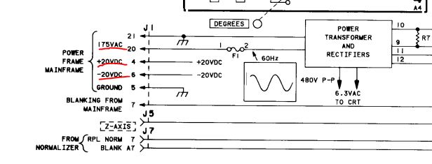
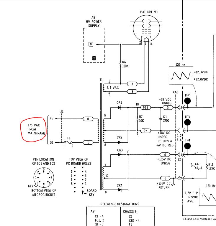
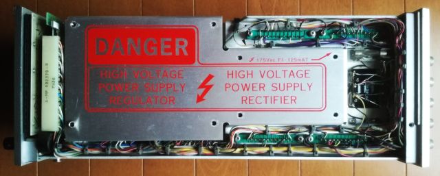
How to get it to work – checked the 8412A manual, and, unfortunately, it needs a whole lot of unusual supply voltages (the 8412A slides into the 8410A/B Network Analyzer mainframe) – not easy to operate it without the mainframe. 175 Volts AC, to drive the CRT and 6.3 VAC heater, and +-20 VDC, for the other circuits.

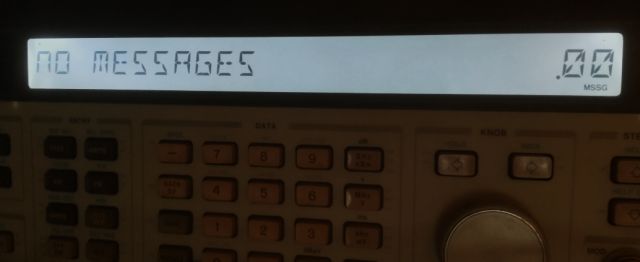
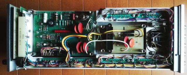
Some pictures of the unit…

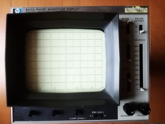
The dangers of high voltage are fairly obvious!!

Quite similar to other HP units – amazing how often they recycled the design!

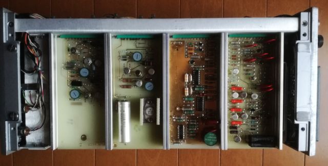
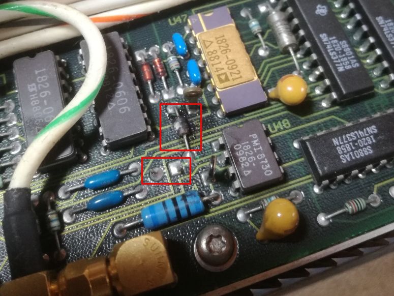
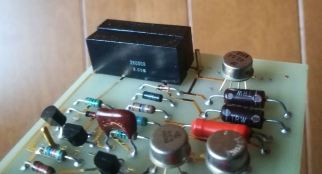
2.000 kOhm, +- 0.05% resistors, a matched pair – not bad! Definitely, a lot of good parts in this unit, including high voltage parts, a good CRT, many semiconductors and transistor pairs, mica capacitors, etc.

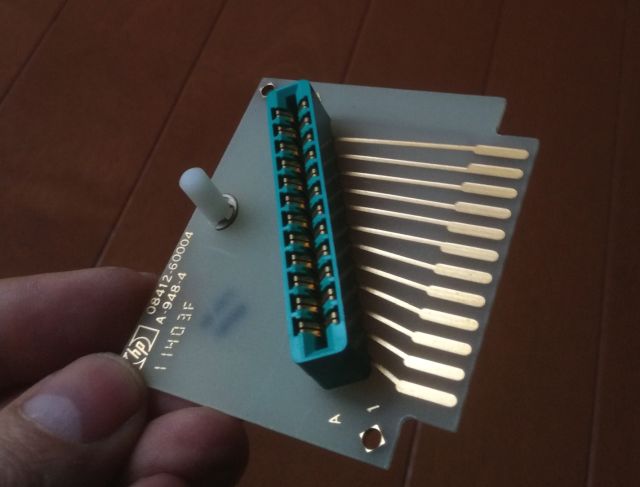
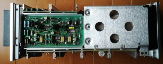
HP even supplied a small test board to make service and adjustment easier! Great!!

HP 8642A Signal Generator: Further repairs

After quite a bit of traveling and other time consuming endeavors, back to the 8642A. After the repairs described earlier, the unit was working fine, until some some escaped from the A2 assembly, which has the low frequency source – one of the tantalums blew. No problem, this can happen for a 30 year old unit that hasn’t been used for while. With close inspection, I discovered not only the defective tantalum, but also two resistors to be defective-burnt.

These resistors are in the supply circuits of some of the amplifiers, to remove ripple from the power supplies.

These are the parts, R17 and the blown C17, and R23. Maybe C27 has some issues as well?

The burnt parts marked in red:

… same case for R23. Note that the resistors had about 12 ohms and 15 ohms, so they did not fail open, and this is why the A2 assembly had no functional defect.

Further tests showed that C27 is perfectly fine. Maybe some overload occurred out the output, or the resistor R23 has some weak design (these are only 50 mW resistors!).

The repair is easy, just put in 22 Ohm resistors (0.4 Watt metal film – don’t have any 19.6 Ohm resistors here, but for the given purpose, 22 Ohms is good enough). The 10 uF tantalums C17 and C27, I replaced by 10 uF multilayer ceramic capacitors.

Carrying out the full self test (Shift-Preset-Shift-SPCL-330-Hz).

It takes a while to test the unit, several minutes, but all tests passed with no issue. Modulation output and amplitudes are fine as well.

As you can tell, I have also fixed the backlight (same as before – some high efficiency white LEDs and two 120 Ohm resistors; keep in mind, the common pin for the backlight is ground, and the bulbs are driven by -5 Volts, so, make sure to get the polarity right).

Last but not least – I also replaced the front frame of the instrument, I had a spare back home in Germany, and carried it over to Japan at the occasion of the last visit in Germany, end of March.