8645A Agile Signal Generator: finally, all fixed

After quite a bit of work with the front panel (see earlier post, massive transport damage), and repair of its most beautiful and complicated inner workings, the remaining item to be fixed: the main output connector (N-type connector). The original one, damaged beyond repair, and the bracket holding it, severely bent, and a broken-off screw stuck in it.

Screening through my parts stock, found a rather old but still good panelmount N connector. It has a slightly different inner construction (the original 8645A has a quite long gold-plated coaxial air-line in the connector; replacement connector has no gold plating), but within reason, this should not matter.

This how it looked before:
8645a damaged connector

The bracket and assembly was fixed back home, in good old Germany, in the mechanical workshop, during xmas vaccation.

Now, looking at the result, quite pleased with the outcome of quite a few hours of work (and some expenses, for a replacement HP System 2 front panel frame, see earlier post):

8645a front fixed

8645a front

8645a n connector

Note that there are two handles now mounted to the unit, not so much for carrying it around (about 70 pounds!), but to protect the front panel.

5372A Frequency and Time Interval Analyzer: ROM images

Always a good idea to back-up the EPROMs of dated test equipment – rarely they fail, but very tough to fix, at least, if it is a less-popular unit. The 5372A is definitely less popular. Let’s make at least the EPROM images publicly available, I hope HP doesn’t mind!

There are 8 EPROMs: 4 pcs 128Kx8 HP p/n 1818-4060, and 4 pcs 512Kx8 HP p/n 1818-3825 (equivalent 27C512).

5372A ROM Rev 2947 Dec 08 1989

These are the hp serials and denominators of the EPROMS:

05372-80032 A7U16
05372-80033 A7U17
05372-80034 A7U18
05372-80035 A7U19
05372-80036 A7U52
05372-80037 A7U53
05372-80038 A7U54
05372-80039 A7U55

5372A Frequency and Time Interval Analyzer: out of sensitivity cal. error – easy fix

For most precise time interval counting, I use a trusty HP 5370A, which has no less than 20 ps single-shot resolution. The 5370A and its inner workings could be discussed for hours (well, pages) here, but this is not the topic of this entry. This is about the 5372A, a much more modern machine – it still measures time intervals, but has a pretty capable build in numerical analyzer. It has a CRT, excellent quality, magnetic deflection, and this provides a nice and sharp green display. It doesnt’t add much weight, because the 5372A is massively heavy anyway, due to all the shielding, and a huge linear transformer. Why did HP use a linear transformer? No idea! Even the most quiet synthesizers can run with some kind of high quality switchmode supplies. Well, in the end, these machines are not build to be carried around but rest, or work, in an adequately thermostated metrology lab.

The 5372A has some very useful functions, not available for many other counters, unless you spent a lot of time developing your on software, work via GPIB; the 5372A can do virtually all of the most exotic tests, just with the single box.

That’s the main CPU, a MC68020 (the first real 32 bit processor ever!!!), and a floating point co-processor, MC68881, and a lot of traces that let the bits flow around.
5372a main cpu

5372a cpu board traces

This one, managed to get it for very little money, with the build-in precision HP 10811 reference OCXO already worth 100, used. And it even has the very desirable Option 030, 2 GHz input. Ideal for measuring locking processes of PLLs (via a triggered frequency vs. time display – shown directly on the screen, as a diagram/graph!), etc.

With the 5372A there are two important things to consider:

(1) It is extremely heavy, and does not ship well, unless it is packages with utmost care. My unit arrived in a big box, and barely made it – don’t even consider international shipment without a lot of bubble wrap, heavy foam, and double-boxes.

5372a box

You can see the box already damaged; and there was just a single layer of bubble wrap; but I was lucky, the machine survived.

5372a unpacked

(2) Second item, never get desperate about the “160 out of sens cal error”. This error is well-known for these units, and the 5373A, and its 99% cause is a dead lithium battery on the CPU board. Just replace the battery, and follow the instructions to calibrate.

These are the main parts: a spare AA Li-SOCl2 cell, the CPU board with the dead battery (Tadiran is a really good quality Li-SOCl2 cell). And the new battery fitted (of presumably lesser, OmniCell, Made in China; but will be fine).

5372a lithium battery

5372a tadiran

5372a new battery

Note that this cell had been changed before, and some solder spilled!!5372a solder
It seems, it didn’t kill the board, but it is removed now.

The calibration, not very spectacular (using a 8904A Source):

5372a sens cal completed

With the calibration done – no error displayed any more.

More detail testing will follow, but according to the self test, all is fine!

5372a self test pass

8663A Synthesized Signal Generator: a 1 year long repair story

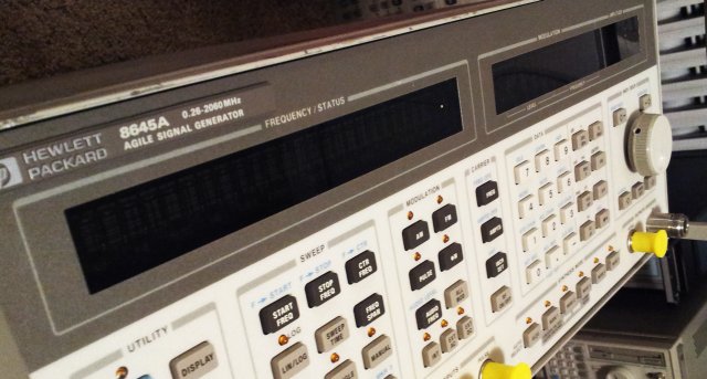
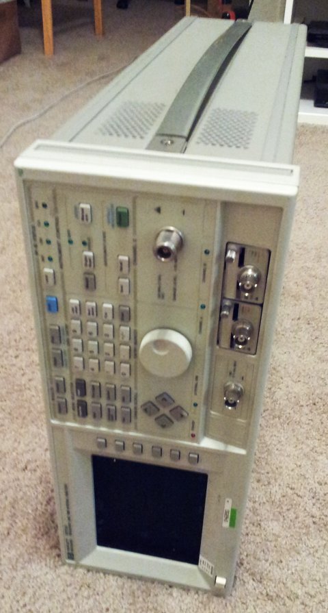
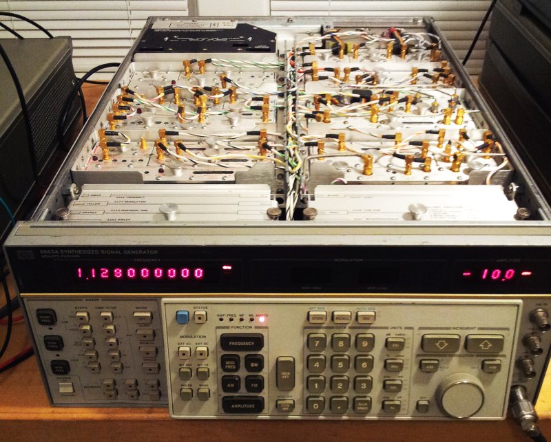
Over a year ago, I got hold of a defective 8663A. It seemed beyond repair, but hardly any equipment is, provided, you put in sufficient effort. The 8663A is certainly worth any resonable effort – it is a marvelous piece of test gear, providing full evidence of human ingenuity. It is said that a team of no less then 20 of the best HP engineers took about 5 years, with full support of the mighty HP organization at the time, to develop the 8662A and later the 8663A generators. Ever since then these were the gold standard for any low close-in noise source, for phase noise measurements, and so on. Keysight is offering a replacement now, the E8663D, about USD 50k, nothing compared to the 8662A or 8663A, for its historic value, and comparing the sheer mass of metal, the amount of gold on the assemblies, and the variety of strange little parts.

8663 internals

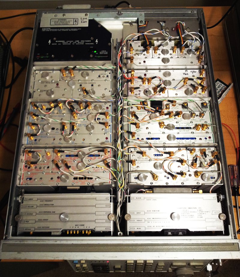
After some analysis, these were the main defects of the unit discussed here:

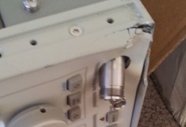
(1) A missing attenuator. The 8663A uses a pair of mechanical attenuators; these come in a set, together with a calibration ROM; with one of the attenuators missing, we might need to check flatness and level accuracy once replaced.

(2) Some intermittent failures of the A6A4 output sum loop. Seems to depend on frequency but not limited to any particular range. Supplied some test signals to the A6A4 assy and the fault really seems to reside with this assembly.

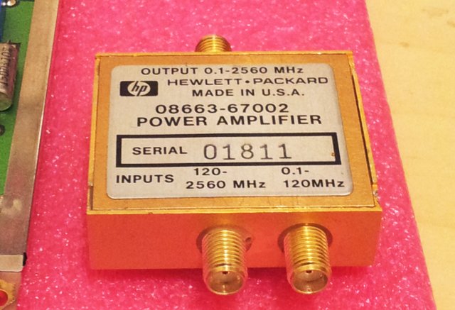
(3) A defective output amp. P/N 08663-67002. This is a real disaster. The output amp is a microwave microcircuit, with HP GaAs FET transistors. Needless to say, such assemblies were very expensive already at their time, and spare assemblies, despite long search, are fully unobtainium.
8663 08663-67002 power amp

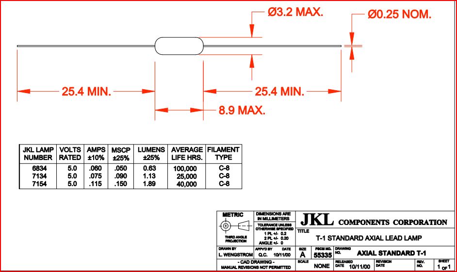
First things first – the attenuator. Found a spare attenuator that should be resonably close to the orgininal one. Did a quick check – it has very flat frequency characteristics anyway, so the ROM calibration coefficients might not be too significant (the 8663A has +-1 dB level spec, but typical accuracy appears to be more like +-0.2 dB; relative levels about +-0.1 dB). Someone tool the attenuator from the ‘dead’ unit, including the bracket – well, I didn’t spent too much time (as you can see) to fabricate a replacement. Good enough.

8663 atten holder

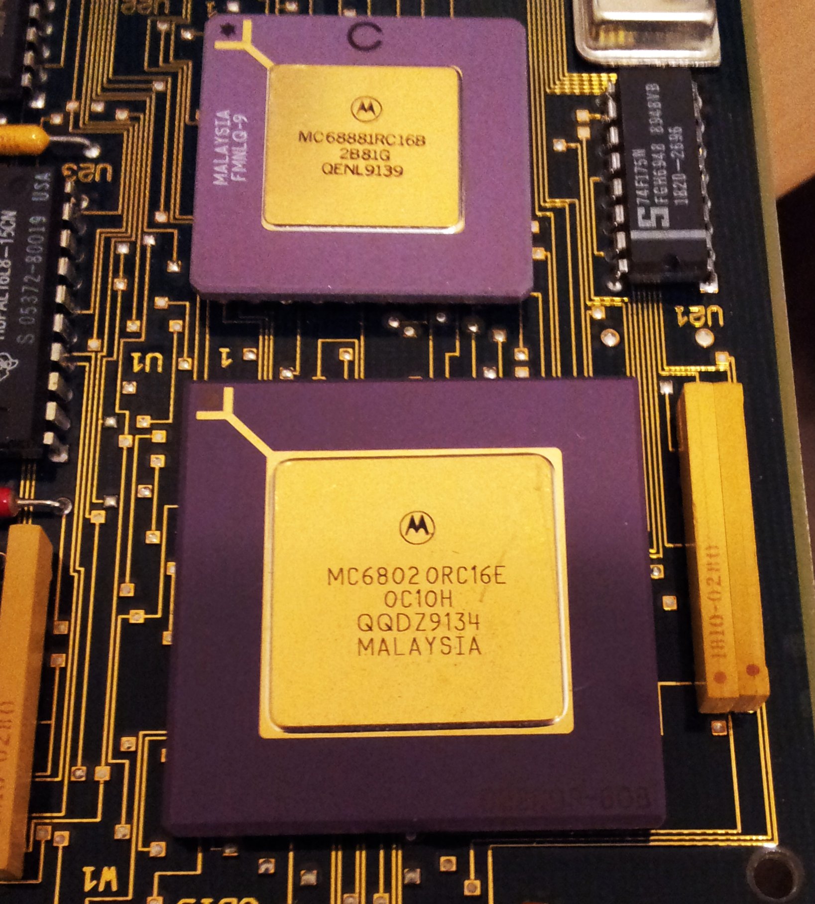
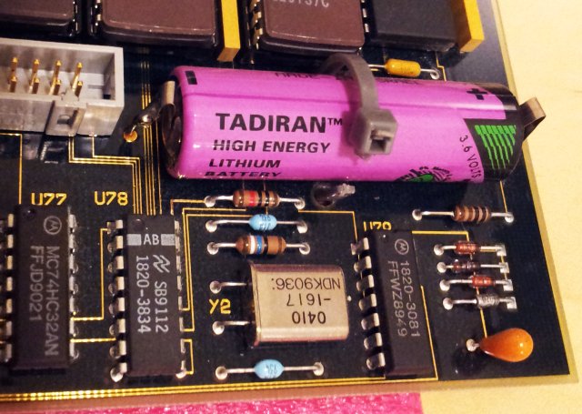
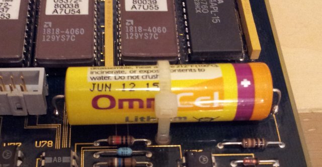
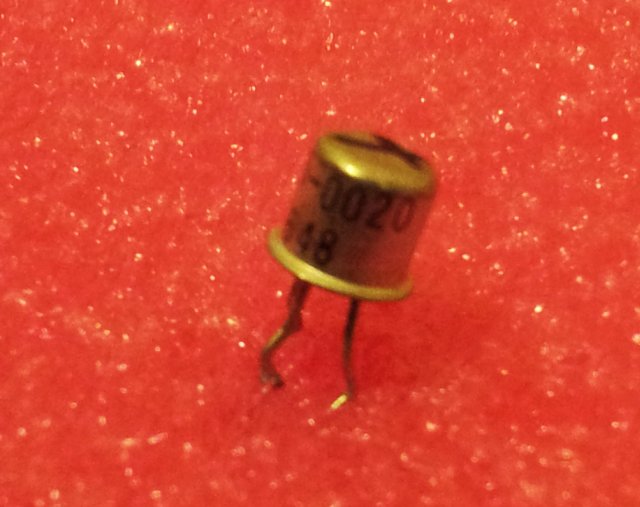
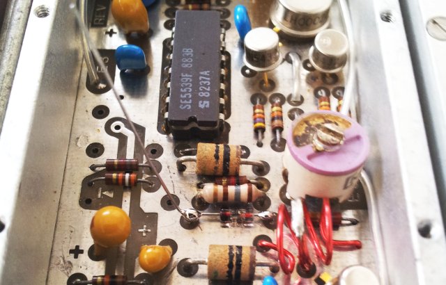
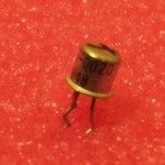
The intermittent fault of the A6A4 assembly – these assembly seem to be the weak point of the 8662/8663 series – I have already fixed a few of these. With schematics around, no big issue to fix – still it took a few hours this time. Turns out, the pre-tune DAC, which is a discrete circuit using 4 FET switches (1 per bit), showed erratic behavior. This was traced to one of the FETs, of the common 1855-0020 type – I took one from an early 80s HP parts units (8569A).

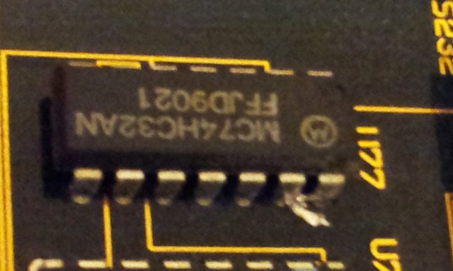
This is the bad guy:
8663 5-20 fet

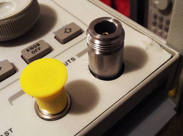
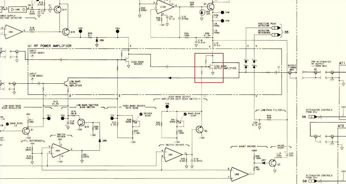
The most critical item, the 08662-67002 amp. This has a low frequency (<120 MHz), and a high frequency input (>120 MHz), which are routed to a common output, providing about 20 dBm of power, at low distortion (about 35 dBc), over the full band from DC to 2.5 GHz.
8663 amp schematic

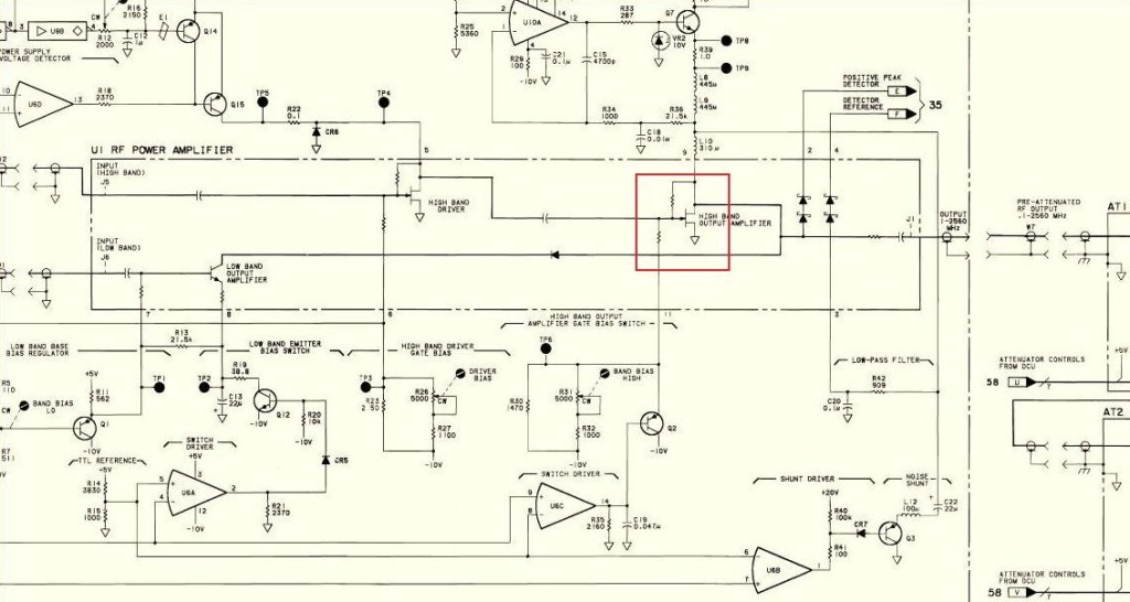
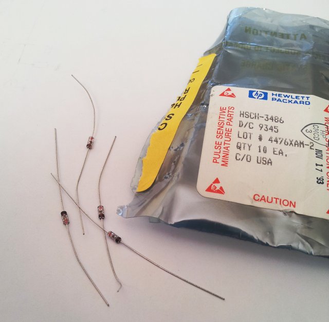
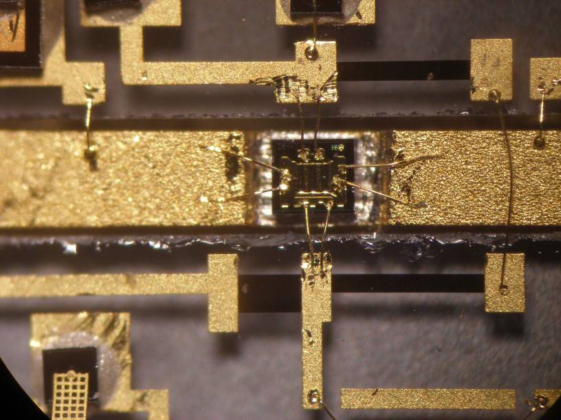
After opening up the microcircuit, it is pretty clear that the last of the FET transistors is blown, and shorted to ground. This is all sapphire substrate, wire bonding, high frequency art. Beyond my capabilities (do you have a wire bonder at home, and a steady hand, and the skill and knowledge? Please teach me!). However, this world is not all bad, and rescue came along, back in good old Europe – in its South-West corner.

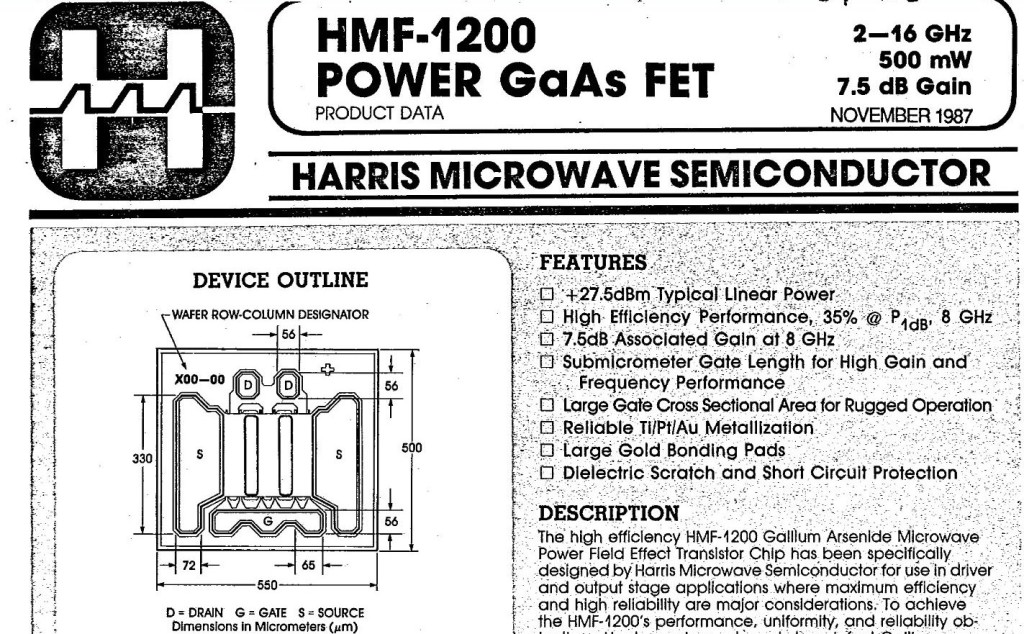
Turns out that a HMF-1200 is a suitable replacement for the proprietary-unknown original HP part.

8663 hmf-1200 gaas fet

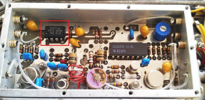
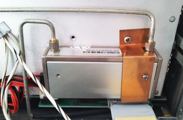
Here the work of the kind friend, who certainly has tremendous skill and is a master in his field:
8663 00912

8663 00929

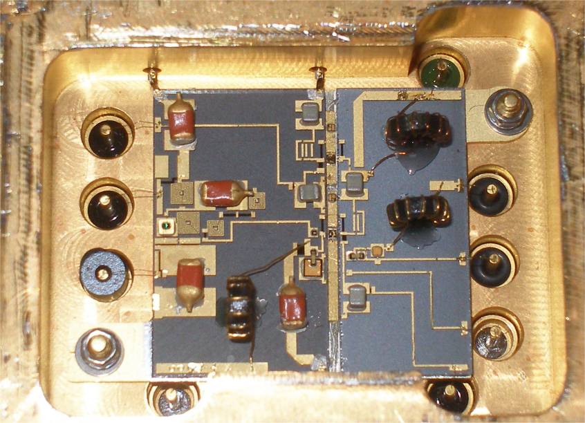
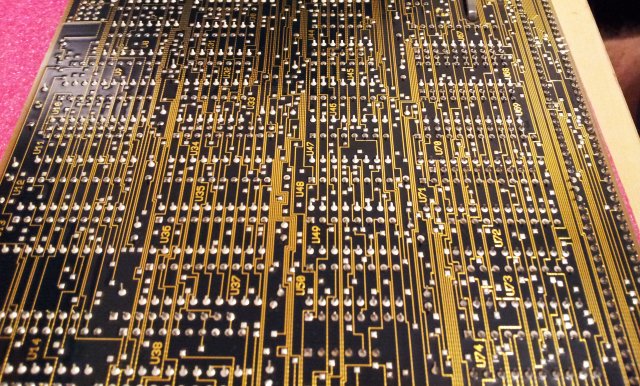
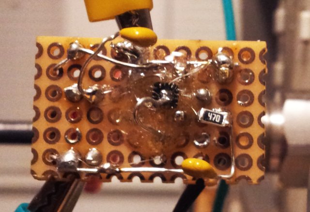
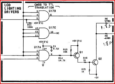
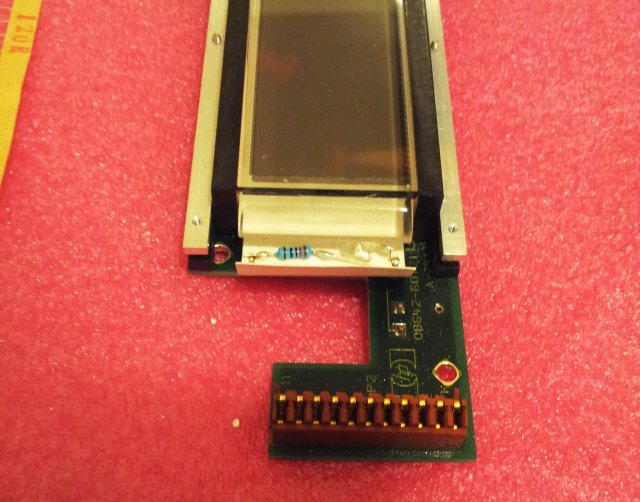
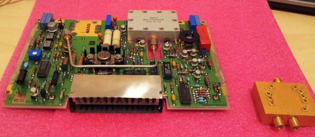
This is the associated board, with a PIN switch, and some bias regulators.
8663 08663-60301 a12a1 output amp brd

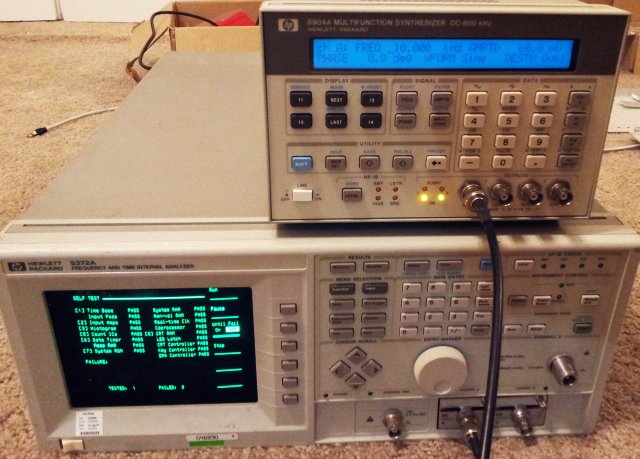
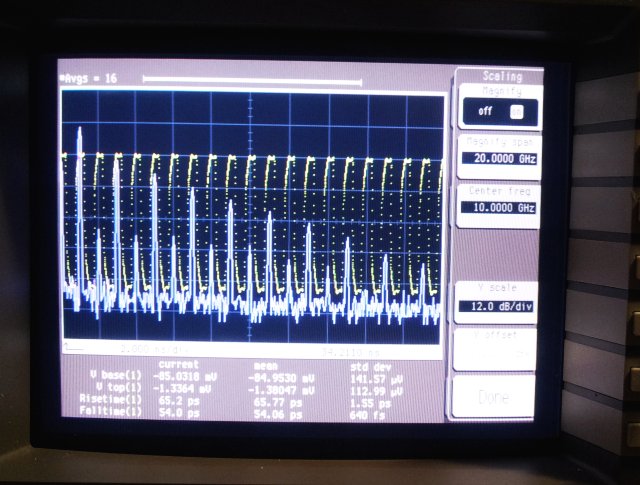
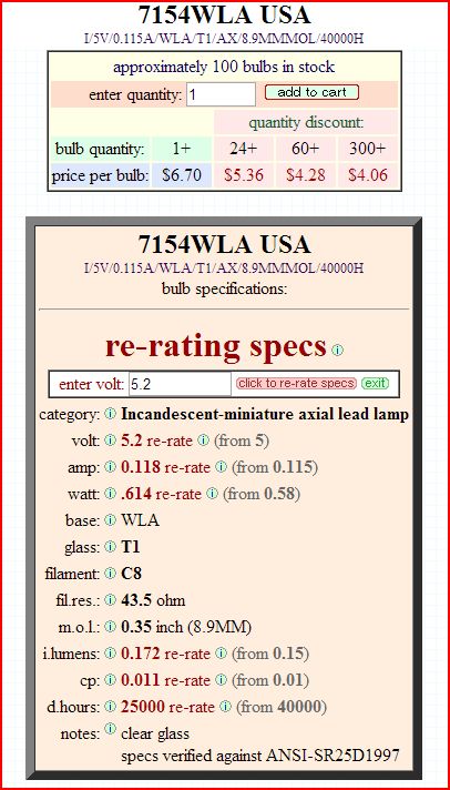
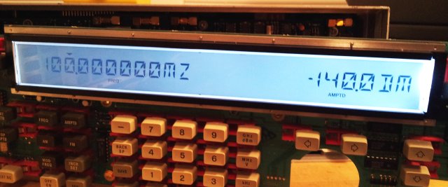
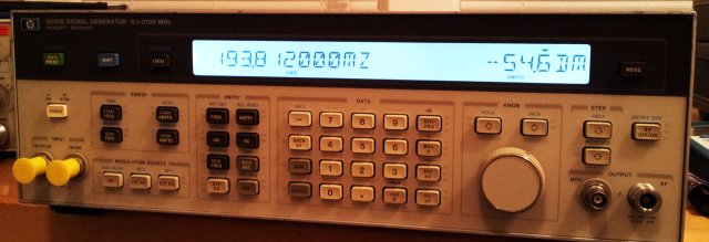
After all these repairs, and some adjustments (which took another few hours; including amp bias, lock detectors, ALC, FM VCO, …), the machine is working again – uptime so far, 48 hours at full power – consuming 500 Watts, and 100 mW at the output. Like powering a 100 W light bulb, from a 500 kW supply…. not quite efficient but a good heat source for the house, during these cold winter days.

8663a internals 2

To come: some flatness and level checks of the attenuator, but don’t expect any bad surprises.

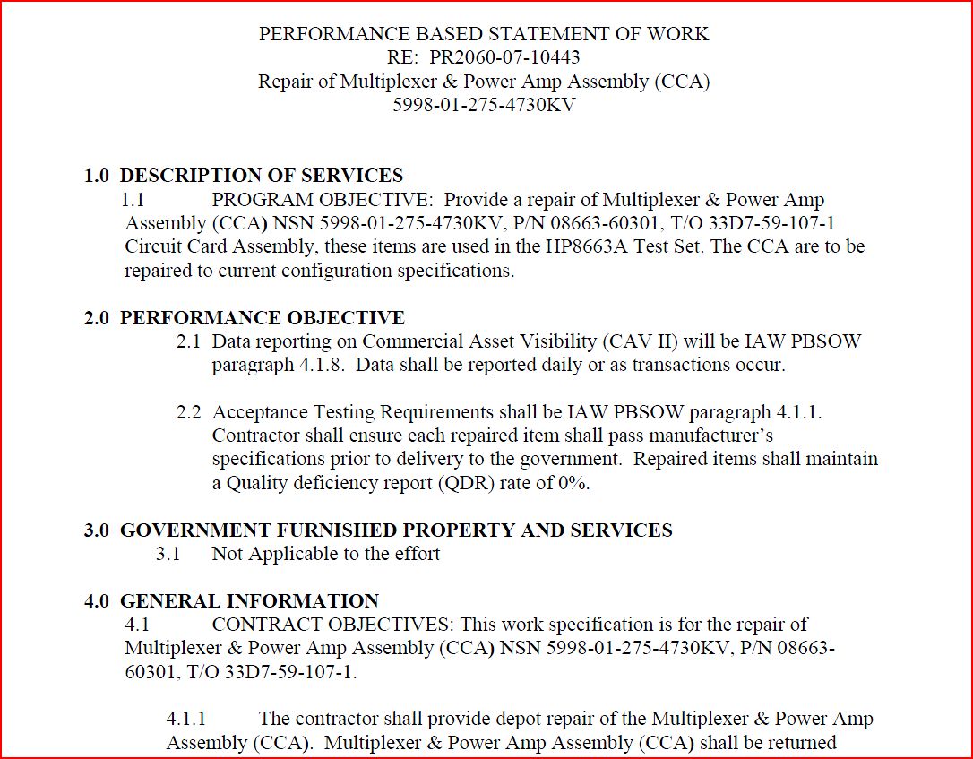
An interesting document, found during the search for spare assemblies – the US Air Force also seems to be looking for repair, for 4 pcs of the amplifier assemblies, for their F15 Tactical Electronic Warfare System Test Set, P/N 001-006730-003.
8663a repair of a 08663-60301
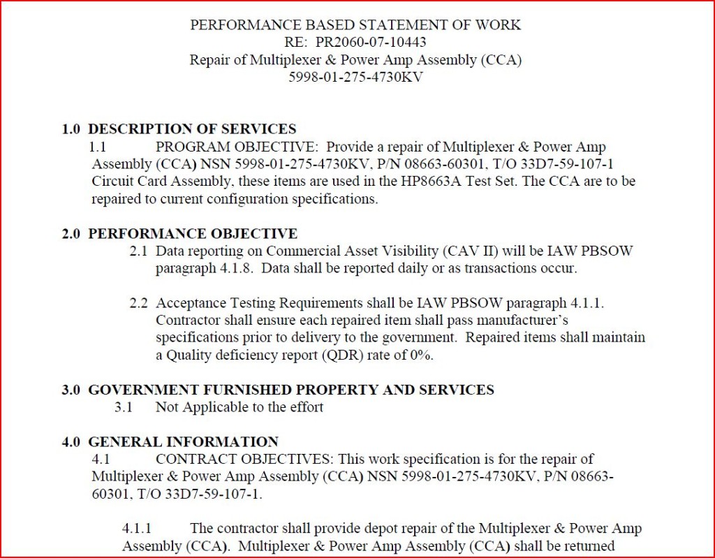
May be a good business opportunity, but not for me!

Micro-Tel MSR-904A Microwave Receiver: AM detector/AGC circuit fix, A3B5 assy

After fully refurbishing and fixing the MSR-904A receiver, and some months of service, another look at the AM detector. It is working fine, but at times, is seems to have some microphonic resonance and random shifts of level. Nothing that prevents use of the machine, but a small flaw worth correcting.

Locating the faulty assembly – pretty obvious when knocking at the A3B5 assembly. This takes in a sample of the 250 MHz IF signal, and performs the AM demodulation, and also generates the AGC signal.

msr-904A a3b5 assy schematic AM detector 250 MHz

These are the inner workings, the signal is first attenuated, about 20 dB, then amplified, about 25 dB, using an Avantek GPD-202.
GPDGPM gpd-202
The signal is then futher amplified via a tuned transistor amplifier.

Demodulation is performed by a zero-bias HP Schottky diode, a HSCH-3486. This was state of the art at the time, and still, there aren’t many diodes around that are any better.

hsch-3486 hsch-3206 hsch-3207

Turns out that this diode must have suffered damage earlier, and it was fixed with a drop of epoxy!

msr-904a a3b5 assy open

The HSCH-3486 are not so common any more (with the SMD package HSMS-2850 being widely used), here a comparison:

hsch-3486 sens

hsms-2850 sens

hsms-2850 hsms-2860

The HSMS-2850 and HSCH-3486 use the same technology – the HSMS-2850 is more or less a SMD version of the earlier HSCH-2486 (glass package, similar to DO-35).

Now, should I replace the flaky diode with a HSMS-2850? Well, after some thought, rather keep the parts as they are, for such a rare instrument. With some effort, this is what I found:

hsch-3486

Glad I didn’t have to buy at USD 20 each, that’s what some vendors are asking for.

A bit of soldering, without taking the whole assembly apart:
msr-904a a3b5 new diode soldered

Finally, a quick sensitivity and microphonic test – no issues at all.

Quite interestingly, someone must have fixed this assembly before – note the ECG opamp, 1991 datecode (it is a LM1458 replacement; for the AGC circuit).

msr-904a a3b5 assy ecg

ADCMP580 Ultrafast Comparator: it’s really fast!!

Some experiments with a tiny part that has remarkable qualities: the Analog Devices ADCMP580. It is a comparator, and a very fast one indeed, based on a SiGe semiconductor.

adcmp580 features

Its features are true extraordinary – everything specified in GHz and picoseconds.
Well, can this be made work without a lot of money invested in a special HF or microwave board? Yes, it can. You just have to keep the wires short:

adcmp580 board

This test board was constructed by first soldering thin wires to the chip, and then mounting it on a small piece of perf board, with some epoxy glue. The output is wires, within less than 2 mm, to a (50 Ohm) SMA connector.

adcmp580 schematic

Measuring the performance characteristics is not an easy task. I used a 54750a sampling scope, with a 54751a 20 GHz bandwidth plug-in.

The comparator is fed by a 8642b signal generator, which is also used to trigger the 54751a plug-in.

At the output, a 13.5 dB attenuator is used, at least for some of the tests, to get best output SWR (to avoid issues caused by reflected signals). However, as it turns out, the 54751a has quite reasonable input SWR, and the connecters are better than it first seemed. So the attenuator can be left out. Still good to have some attenuators at the 54751a input, remember, this can only handle +-2 V, and no ESD!

adcmp 500 mhz square

adcmp 2 ghz square

In these tests, “squaring up” a 500 MHz and 2 GHz (!) signal. Rise and fall time are about 50 ps, not bad at all for the simple construction.

adcmp fft

FFT shows bandwith to 10 GHz and up.

Output power is also quite useful, 400 mV Vpp.

LinuxCNC EMC2 HAL Files: 3 axis mill, 2 axis lathe with encoders, jog wheel, axis compensation, camera view

Due to frequent requests – here are the configuration files for my LinuxCNC (EMC2) controlled mill and lathe.

The mill is a 3-axis machine, with stepper motors and jog wheel (see earlier post).

emc2 linuxcnc fkm 3 axis mill hal with jog 150101

The lathe has 2 axis, stepper motors, and digital readouts. No feedback on the readouts, but they are great for highest precision work. Configuration files also include the setup for spindel-synchronized movement and spindle speed readout. I have run spindle-synchronized toolpaths for cutting regular and tapered threads with no issues at all, up to a few 100 RPM. The GUI (axis) is also configured for use with a little camera that is very handy to set the coordinates of the tools.

emc2 linuxcnc jet lathe with optical scale and spindel index 150101

Any questions, please ask. These files are meant as a source code collection for you to code your own HAL files, etc.; if you need help with a particular configuration, feel free to contact me.

Please consider that some fragments of the code might be copyrighted by others – however, I have modified it so many times that it is virtually impossible to trace back.
My contribution to these HAL files: You can copy, modify, distribute and perform the work, even for commercial purposes, all without asking permission. The work may not be free of known copyright restrictions in all jurisdictions. Persons may have other rights in or related to the work, such as patent or trademark rights, and others may have rights in how the work is used. I make no warranties about the work, and disclaim liability for all uses of the work, to the fullest extent permitted by applicable law.

Rong Hua (Bianhuan) “50 Watt” Travel Adapter: not enough iron, for this “wattage”

In interesting find, Made in China, a 50 Watt travel adapter.

autotrans sc-20c a

autotrans sc-21c

autotrans sc-21c receptacle

autotrans plug

This is used to convert 220 V (despite the US plug!) to 110 V – same device also seems to exist for conversion from 110 to 220 V.

The build quality is exactly what you expect for less than USD 7. A crude plastic case, two screws, no protection circuits or fuses, and a rather small transformer.

autotrans inside

Total weight of the transformer – about 140 g.

Looking at some transformer tables, this is about 6-10 VA (=”Watt”, if you wish) nominal size. For autotransformers like this, the nominal size needs to be converted to the actual power rating, by using the conversion ratio (voltage ratio). P_nominal=P_actual*(1-voltageratio). I.e., for a 220 to 110 Volts transformer, the ratio is 0.5, and a 10 VA nominal transformer can handle 20 VA if configured as an autotransformer.

Quite obviously, 20 VA is not 50 VA – please use these these transformers with great caution, and only for really small appliances. Never leave it plugged in unattended, it might catch fire any time if overloaded, or if it fails!

HPAK 8642B Synthesized Signal Generator: backlight replacement

The 8642B is an excellent generator, very clean, at least at offsets >1 kHz, hard to beat. It is also very heavy, thanks to a special modular concept that HP was pushing at the time. Their intention was to make the unit more serviceable, with the result that the generator is super heavy, and so expensive that it never was a real commercial success for HP. Frequency range is from below 100 kHz, to 2115 MHz. Pretty useful, with amplitudes from -140 dBm to 20 dBm.

The generator has a rather large (for the time) LCD display – fully story can be found in the HP Journal, December 1985.

backlight assy

backlight detail

The backlight has a very thoroughly designed light diffusor, which directs light from two 5V axial bulbs evenly to the LCD. Sure enough, these bulbs can burn out.

Some webpages claim that such bulbs would only last a few 100, maybe 1000s of hours, but such statements are incorrect. The bulbs used, 5 V, 115 mA, will typically last about 40000 hours, much longer than common household light bulbs.

bulb
t-1 axial lamp

These little bulbs have 1.9 Lumen each, not bad. To replace with a LED, 14000 mcd, at 25 deg angle, are about 2.2 Lumen. Close enough.

Found some 3 mm superbright white LEDs:

ligitek superbright 3 mm white

0.04 USD each!! Amazing!

Also these won’t least forever, white LEDs do lose intensity over time, like, 50% remaining intensity after 20000 hours.
I decided to run them below the rated current, at about 16 mA (120 Ohm series resistor with 5.2 V supply). Maybe this will make them last a bit longer.

Note that the backlight is software-controllable (special functions 134 and 234). This is how it is implemented (let me know if you need to full schematics of the 8642A or 8642B):

8642b backlight driver

The resistors (1.8 Ohm) make sure that the lamps operate at 5.0 Volts, not 5.2 Volts, and don’t interfere with the operation of the LEDs. Quite amazingly, running at 5.2 V vs. 5.0 V would reduce the life span from 40000 hours, to 25000 hours!

5-0 volts bulb
5-2 volts bulb

Agilent sold these bulbs for about USD 18 each!!

No mechanical modification of the 8642B at all, the LED and the resistor fit well into the cavity (don’t worry about the lens of the LED – the light will find its way.

8642b backlight mod

The result:

8642b backlight uneven

– not to my full satisfaction (non-uniform brightness, looks a bit dark on the left hand side, albeit, very easy to read).

After a bit of head scratching – turns out I soldered in the left LED with incorrect polarity – so it can’t work.

With this little mistake corrected, all is good:

8642b backlight

Now, let’s hope that these LEDs will last. Never mind, I have a bag of spares!

Note: the display assembly is said to be rather ESD sensitive. Make sure not to damage it!